Unlock instant, AI-driven research and patent intelligence for your innovation.
Method and apparatus for measuring a parameter of a vehicle electrical system
What is Al technical title?
Al technical title is built by PatSnap Al team. It summarizes the technical point description of the patent document.
a technology of electrical parameters and vehicle electrical systems, applied in the direction of impedence measurement, resistance/reactance/impedence, instruments, etc., can solve the problems of relatively small cable resistance and typically inability to measur
Inactive Publication Date: 2006-12-26
MIDTRONICS
View PDF422 Cites 75 Cited by
Summary
Abstract
Description
Claims
Application Information
AI Technical Summary
This helps you quickly interpret patents by identifying the three key elements:
Problems solved by technology
Method used
Benefits of technology
Benefits of technology
Enables accurate and efficient measurement of cable resistances, reducing voltage drops and improving power delivery to loads, thereby aiding in diagnosing and maintaining electrical systems without the need for cumbersome high-current testing.
Problems solved by technology
Because the cable resistance is relatively small it typically cannot be measured using a standard ohm meter or other techniques which are normally used to measure resistance.
However, this is cumbersome and requires components capable of handling the large current.
Method used
Image
Click on the blue label to locate the original text in one second.
Reading with bidirectional positioning of images and text.
Examples
Embodiment Construction
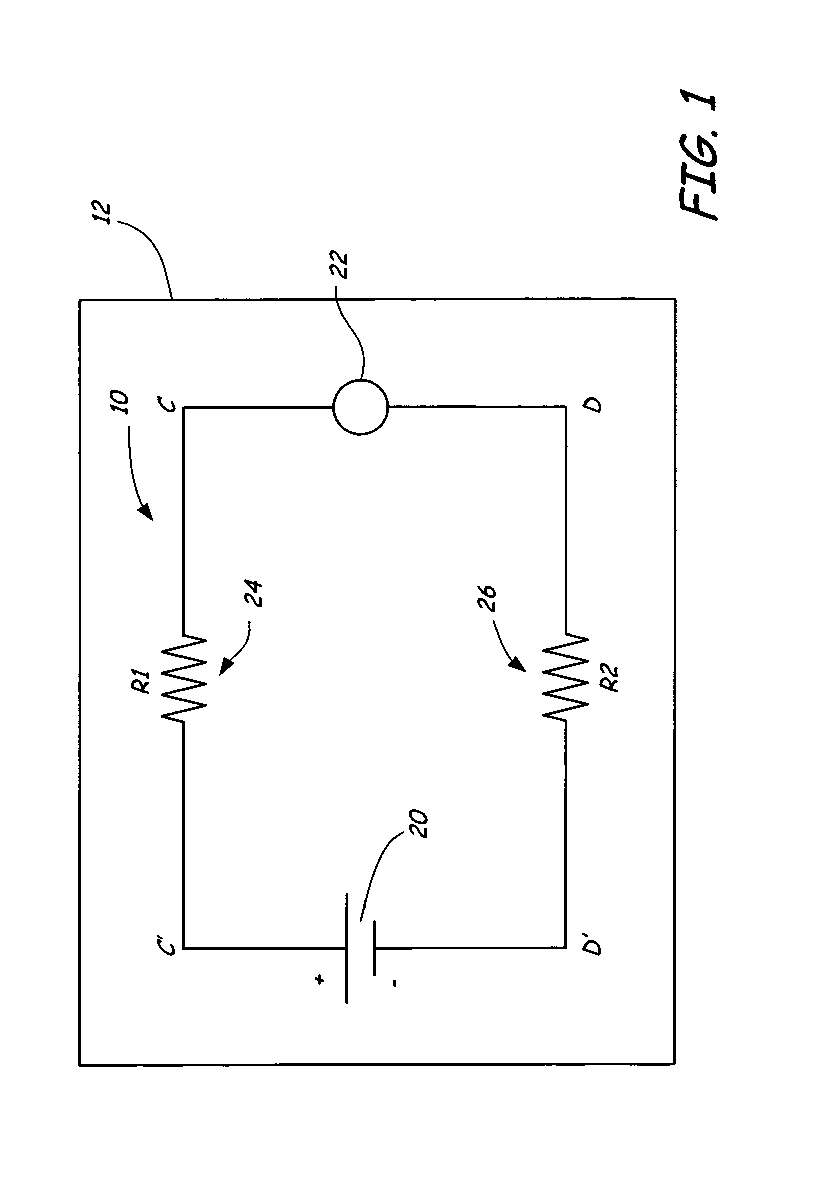
[0010]FIG. 1 is a diagram of an electrical system 10 of large equipment 12 such as a heavy truck. Electrical system 10 includes a battery 20, a high current load 22 and cables 24 and 26. Cables 24 and 26 have resistances R1 and R2, respectively and connect load 22 to battery 20. FIG. 1 also shows connection points C, D and C′, D′. Connections C and D are across load 22 and connections C′ and D′ are cross battery 20.
[0011]As discussed in the Background section, the resistances R1 and R2 of cables 24 and 26 can have a significant impact on the amount of power which can be delivered to load 22. Even if the resistance values are relatively small, because a relatively large current passes through cables 24 and 26, the resultantvoltage drop can significantly reduce the voltage at points C and D and therefore the amount of power (or voltage) which can be delivered to load 22. In industrial equipment, it is often desirable to measure the resistance R1 and R2 of cables 24 and 26, respective...
PUM
Abstract
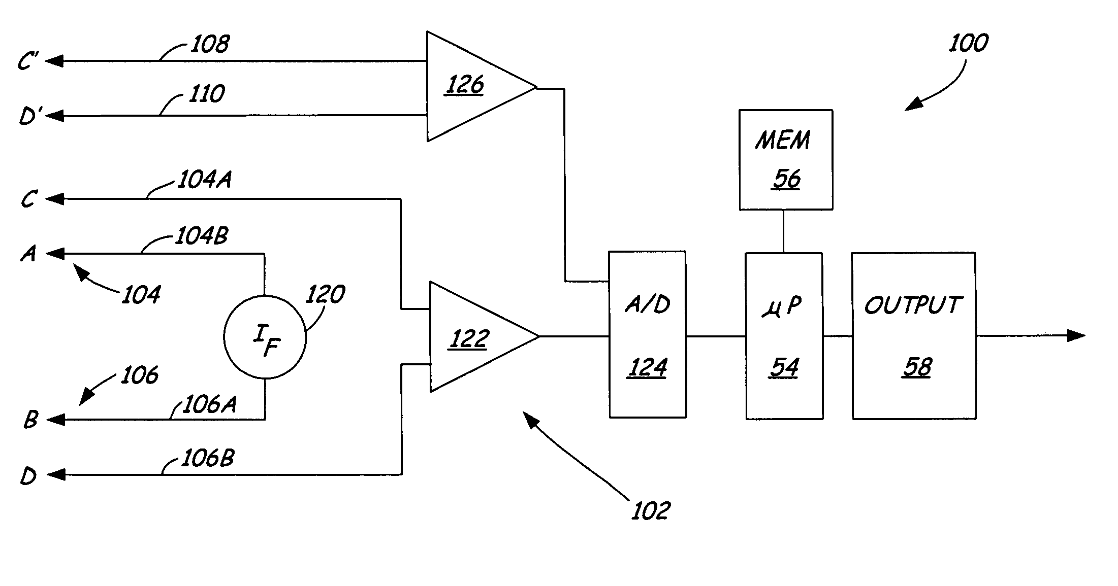
An apparatus for measuring electrical parameters for an electrical system measures a first and second parameters of the electrical system between connections to the electrical system. A processor determines a third electrical parameter of the electrical system as a function of the first parameter and the second parameter.
Description
BACKGROUND OF THE INVENTION[0001]The present invention relates to the measurement of electrical parameters of a vehicle electrical system. More specifically, the present invention relates to measuring an electrical parameter of an electrical system of a vehicle through the use of multiple measurements.[0002]Electrical systems, such as those which are used in automotive vehicles, consist of a number of discreet components or systems which are interconnected. Techniques for measuring and utilizing parameters, such as dynamic parameters, of electrical systems are shown and disclosed in U.S. Pat. No. 3,873,911, issued Mar. 25, 1975, to Champlin, entitled ELECTRONIC BATTERY TESTING DEVICE; U.S. Pat. No. 3,909,708, issued Sep. 30, 1975, to Champlin, entitled ELECTRONIC BATTERY TESTING DEVICE; U.S. Pat. No. 4,816,768, issued Mar. 28, 1989, to Champlin, entitled ELECTRONIC BATTERY TESTING DEVICE; U.S. Pat. No. 4,825,170, issued Apr. 25, 1989, to Champlin, entitled ELECTRONIC BATTERY TESTING...
Claims
Application Information
Patent Timeline
Application Date:The date an application was filed.
Publication Date:The date a patent or application was officially published.
First Publication Date:The earliest publication date of a patent with the same application number.
Issue Date:Publication date of the patent grant document.
PCT Entry Date:The Entry date of PCT National Phase.
Estimated Expiry Date:The statutory expiry date of a patent right according to the Patent Law, and it is the longest term of protection that the patent right can achieve without the termination of the patent right due to other reasons(Term extension factor has been taken into account ).
Invalid Date:Actual expiry date is based on effective date or publication date of legal transaction data of invalid patent.
