
Envelope modulator for haptic feedback devices

Inactive Publication Date: 2006-12-26
IMMERSION CORPORATION
View PDF78 Cites 119 Cited by
  • Summary
  • Abstract
  • Description
  • Claims
  • Application Information

AI Technical Summary

Benefits of technology

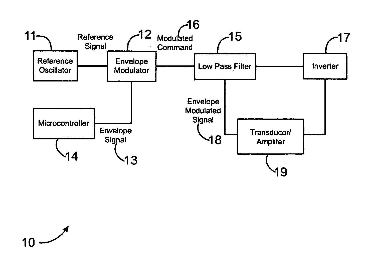
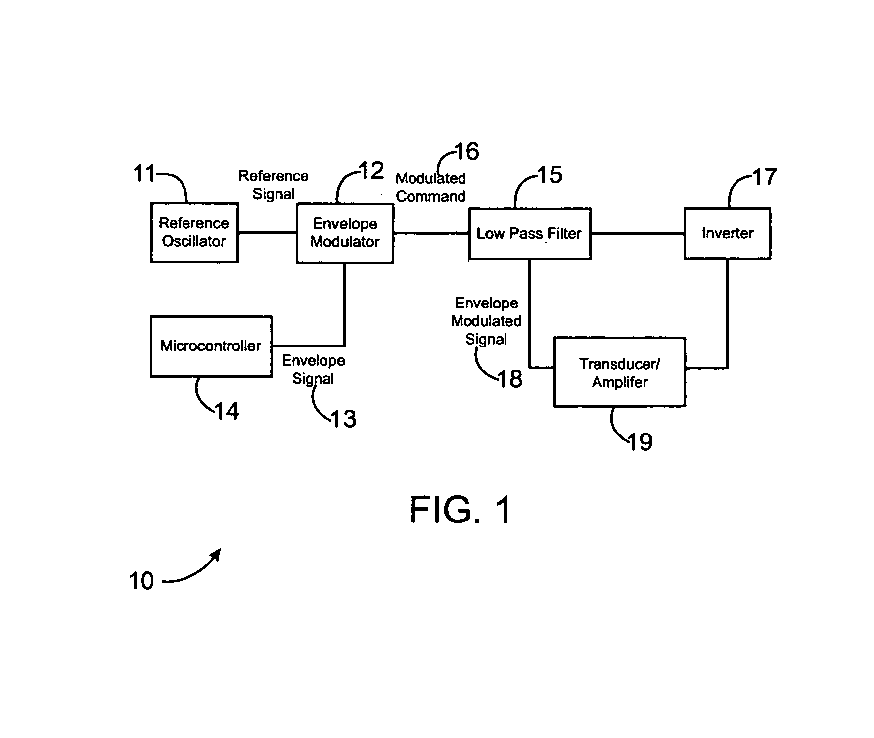
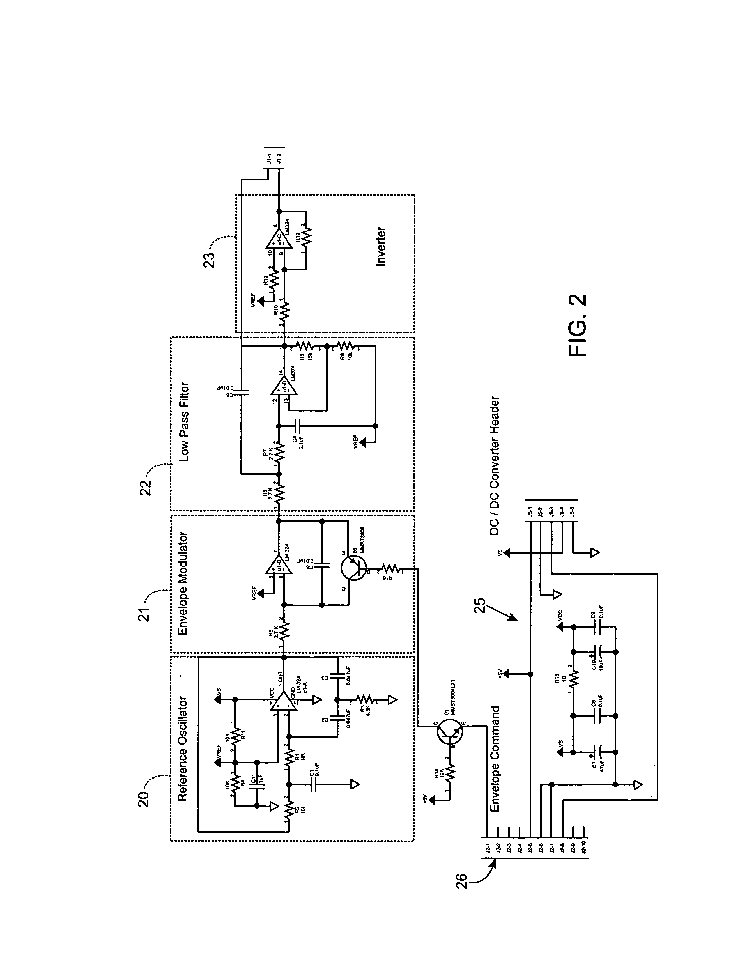
[0007]In accordance with one aspect of the present invention, an amplitude modulator circuit comprises a reference oscillator and an envelope modulator coupled to the reference oscillator for receiving a reference signal. A microcontroller is coupled to the envelope modulator for providing an envelope signal to the envelope modulator and a low pass filter is coupled to the

Problems solved by technology

In portable computer or electronic devices, such as laptop computers or personal digital assistants (PDAs), mice typically have too large a workspace to be practical.
One problem with current haptic feedback devices is that tactile sensations output to the user tend to be more effective in particular frequency ranges and are less effective in other frequency ranges, thus causing haptic sensations to feel uneven and inconsistent to the user over broad frequency ranges.

Method used


Image

  • Envelope modulator for haptic feedback devices
  • Envelope modulator for haptic feedback devices
  • Envelope modulator for haptic feedback devices

Examples


Embodiment Construction

[0015]The present invention is an alternative embodiment of an envelope modulation approach referred to in patent application Ser. No. 09 / 908,184, filed Jul. 17, 2001, which is incorporated herein by reference in its entirety for all purposes. That invention as well as the one described herein, provides methods used to modulate a high frequency signal, suitable for driving a vibrotactile transducer, with a lower frequency signal that contains tactile information. The composite or modulated signal is used to drive an actuator that conveys the lower frequency tactile information to the human user via electrical amplification that drives a transducer, thereby mechanically conveying the tactile information to the user. The high frequency signal oscillates at a frequency that is close to the resonant frequency of the mechanical actuator driven by the transducer, and hence the haptic sensations benefit from mechanical amplification caused by the resonant signal. In patent application Ser....


PUM


Abstract

An amplitude modulator circuit includes a reference oscillator and an envelope modulator coupled to the reference oscillator for receiving a reference signal. A microcontroller is coupled to the envelope modulator for providing an envelope signal to the envelope modulator and a low pass filter is coupled to the envelope modulator for receiving a modulated command from the envelope modulator. An inverter is coupled to the low pass filter for receiving a low passed envelope modulated signal from the low pass filter and a transducer or amplifier is coupled to the inverter and the low pass filter for receiving an inverted low passed signal and the low passed envelope modulated signal.

Description

CROSS-REFERENCES TO RELATED APPLICATIONS[0001]This application claims benefit of U.S. Provisional Application No. 60 / 309,913 filed Aug. 2, 2001, the disclosure of which is incorporated by reference in its entirety. This application is a continuation-in-part of U.S. application Ser. No. 09 / 908,184 filed Jul. 17, 2001.BACKGROUND OF THE INVENTION[0002]The present invention relates generally to the control of haptic feedback interface devices that interface a user with a computer device.[0003]Humans interface with electronic and mechanical devices in a variety of applications, and the need for a more natural, easy-to-use, and informative interface is a constant concern. In the context of the present invention, humans interface with computer devices for a variety of applications. One such application is interacting with computer-generated environments such as games, simulations, and application programs. Computer input devices such as mice and trackballs are often used to control a curso...

Claims


Application Information

Patent Timeline
IPC IPC(8): G09G5/00G06F3/00G06F3/01
CPCG06F3/016H03C1/36
Inventor TIERLING, KOLLIN M.
Owner IMMERSION CORPORATION
Learn More