Waterlight connector

a connector and water light technology, applied in the direction of securing/insulating coupling contact members, coupling device connections, electrical devices, etc., can solve the problems of wires impairing insertion efficiency, adversely affecting the sealing between the housing and the plug, etc., and achieve the effect of efficient insertion of terminal fittings

Inactive Publication Date: 2007-01-02
SUMITOMO WIRING SYST LTD
View PDF9 Cites 46 Cited by
  • Summary
  • Abstract
  • Description
  • Claims
  • Application Information

AI Technical Summary

Benefits of technology

[0009]The groove between the outer peripheral surface of the resilient plug and the outermost wire insertion hole absorbs the resilient deformation of the resilient plug and substantially prevents the wire insertion holes from the window holes of the plug holder. Thus, the terminal fittings and the respective wires can be inserted efficiently through the resilient plug.
[0012]Grooves preferably are formed in both a surface of the resilient plug to face the back surface of the accommodation recess and the surface of the resilient plug to substantially face the plug holder. Further, pressing members preferably are provided on both the back surface of the accommodation recess and the resilient-plug holder. The pressing member on the back surface of the accommodation recess is pressed at least partly into the grooves when the resilient plug is accommodated into the accommodation recess. Thus, a deformation absorbing area of the rubber plug along the longitudinal direction of the wire insertion holes extends both to sides of the wire insertion holes towards the plug holder and to sides of the wire insertion holes towards the bottom surface of the accommodation recess. Therefore, the terminal fittings and the wires can be inserted more easily through the rubber plug.
[0015]The pressing members preferably are tapered or converging towards their leading ends. Thus, the pressing members can be pressed smoothly into the grooves even if the entrances of the grooves become narrower as the resilient plug is urged into the accommodation recess.
[0017]The grooves preferably surround all the wire insertion holes and absorb the resilient deformation of the resilient or rubber plug that would otherwise act on the wire insertion holes. Thus, the wire insertion holes will not be narrowed by the resilient deformation. As a result, the terminal fittings can be inserted efficiently.

Problems solved by technology

The wire insertion holes that are displaced most can interfere sufficiently with the terminal fittings and the wires to impair insertion efficiency.
Therefore, the grooves could adversely affect sealing between the housing and the plug.

Method used


Image

  • Waterlight connector
  • Waterlight connector
  • Waterlight connector

Examples


Embodiment Construction

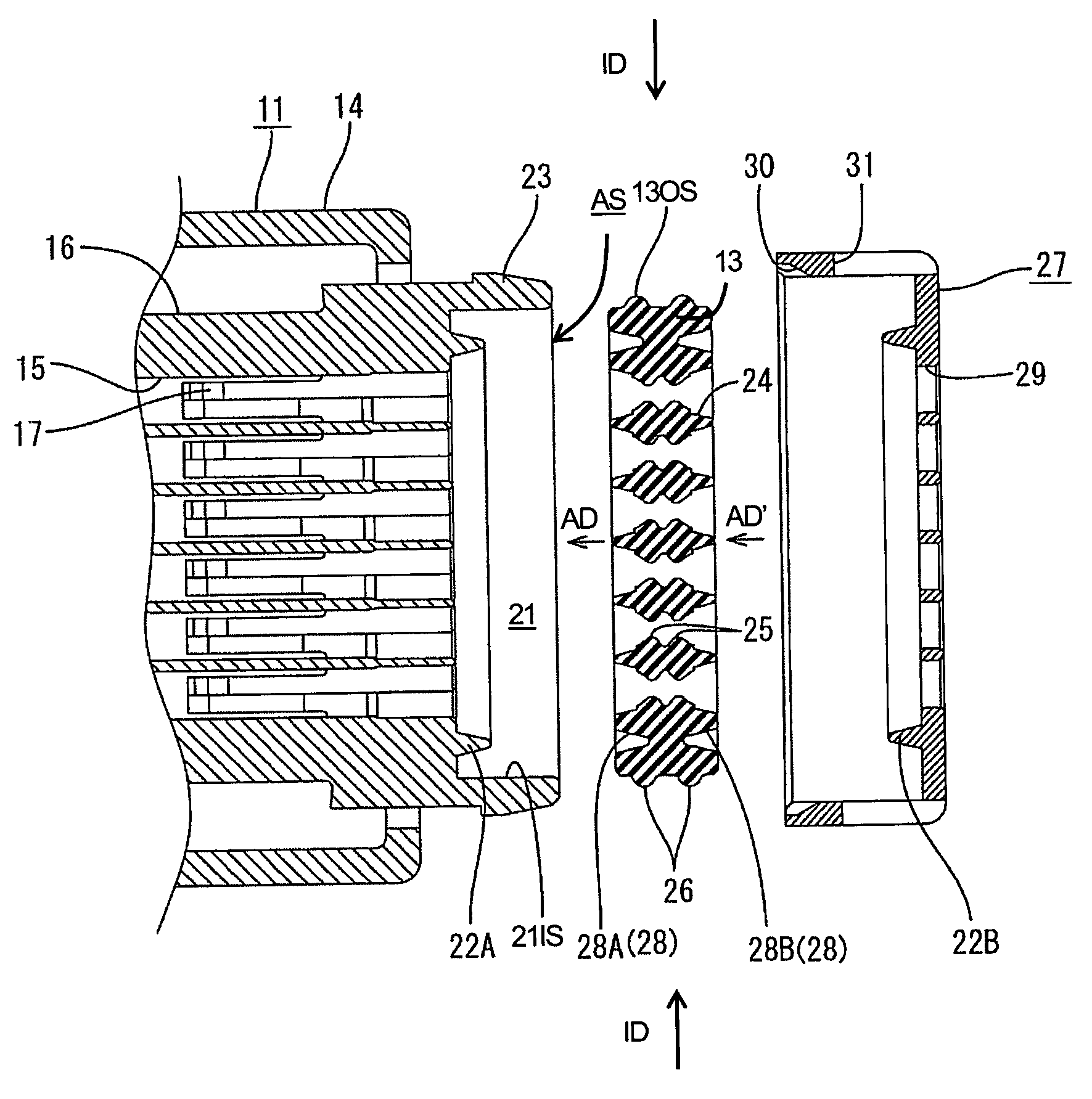
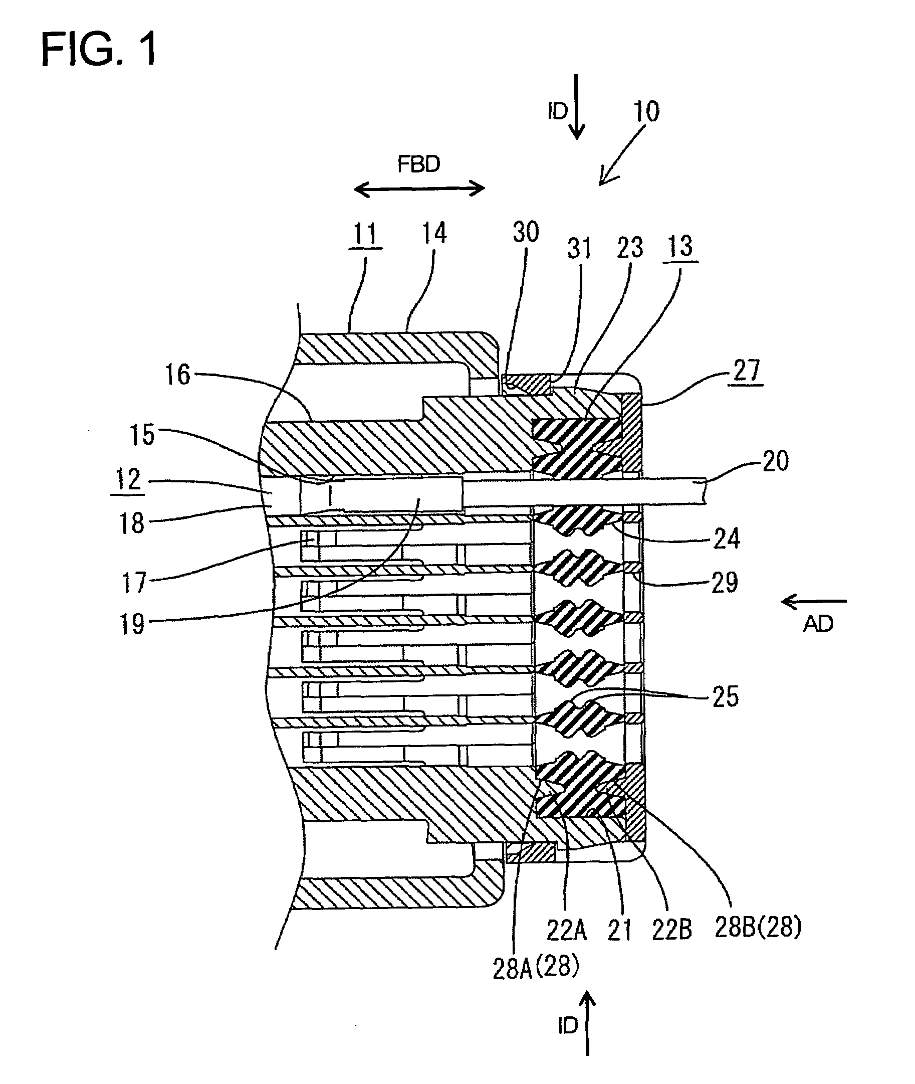
[0026]A watertight connector according to the invention is identified by the numeral 10 in FIG. 1. The watertight connector includes a housing 11, terminal fittings 12 and a resilient or rubber plug 13. The left end of the watertight connector 10 in FIG. 1 is connectable with an unillustrated mating connector and is referred to herein as the front.

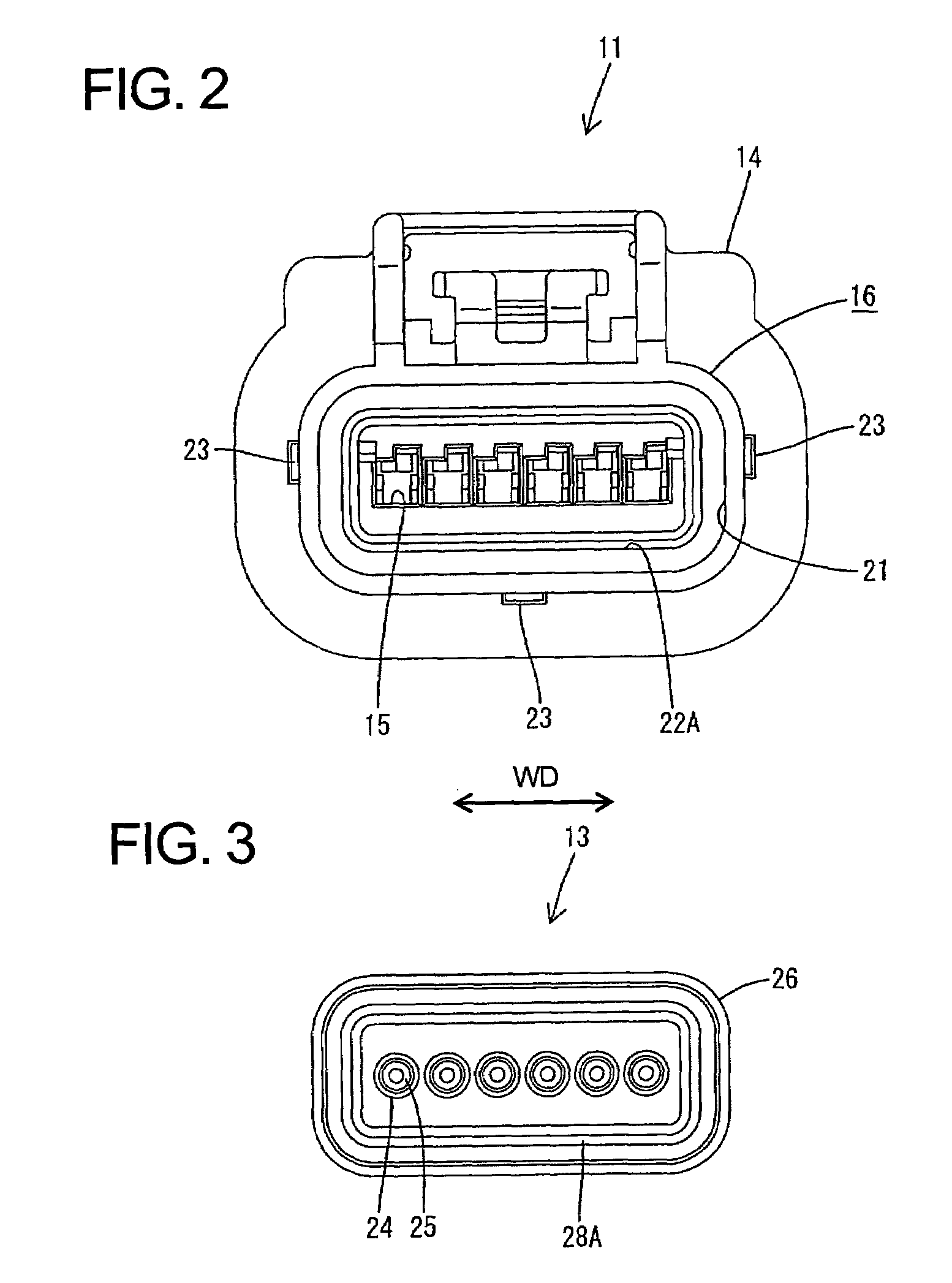
[0027]The housing 11 is made e.g. of a synthetic resin and is formed to define a block shape, as shown in FIGS. 1 and 2. The housing 11 has an outer tube 14 and an inner tube 16 disposed within the outer tube 14. Cavities 15 extend in forward and backward directions FBD through the inner tube 16 and are arranged substantially side by side along width direction WD, which is substantially normal to the forward and backward directions FBD. A lock 17 is provided in each cavity 15 for retaining the female terminal fittings 12 in the respective cavities 15. As shown in FIG. 7, each female terminal fitting 12 is formed by bending or press-working...


PUM


Abstract

Resilient deformation of a rubber plug (13) can be absorbed by a housing-side groove (28A) and a holder-side groove (28B) formed to surround all wire insertion holes (24), thereby preventing the displacements of the wire insertion holes (24). Thus, a reduction in operability at the time of inserting female terminal fittings (12) and wires (20) through the rubber plug (13) can be avoided. Further, a housing-side pressing portion (22A) and a holder-side pressing portion (22B) are pressed into the housing-side groove (28A) and the holder-side groove (28B) over the entire periphery to press the rubber plug (13) into contact with the inner surface of an accommodation recess (21), sealability between a housing (11) and the rubber plug (13) can be ensured.

Description

BACKGROUND OF THE INVENTION[0001]1. Field of the Invention[0002]The invention relates to a watertight connector with a resilient plug.[0003]2. Description of the Related Art[0004]U.S. Pat. No. 6,183,296 discloses a watertight connector with a one piece rubber plug. This connector has a housing with a plurality of cavities and an accommodation recess is formed in the rear end surface of the housing. A one-piece rubber plug is accommodated in the accommodation recess of the housing and has wire insertion holes at positions corresponding to the cavities. The rubber plug is pressed by a rubber-plug holder formed with window holes at positions corresponding to the cavities. Wires connected with terminal fittings are inserted through the wire insertion holes of the rubber plug. As a result, sealing is achieved between the outer peripheral surface of the rubber plug and the inner peripheral surface of the accommodation recess and between the inner peripheral surfaces of the wire insertion ...

Claims


Application Information

Patent Timeline
Patent Type & Authority Patents(United States)
IPC IPC(8): H01R13/40
CPCH01R13/5208
Inventor YAMASHITA, KAZUNORI
Owner SUMITOMO WIRING SYST LTD
Why Eureka
Try Eureka