Furniture assembly jig

Active Publication Date: 2014-01-30
ASHLEY FURNITURE IND INC
View PDF4 Cites 10 Cited by
  • Summary
  • Abstract
  • Description
  • Claims
  • Application Information

AI Technical Summary

Benefits of technology

[0007]The present invention is directed to a furniture jig for assembling the components of a furniture item including assembly of a seat box frame and stretching springs or an elastomeric webbing between the components of the seat box frame. The webbing can comprise a network of interconnected elastomeric strands that can be elongated when a weight is placed on the webbing and return to their original length when the weight is removed. In an embodiment of the present invention, the furniture jig generally comprises, a furniture frame positioning portion and a spring stretcher. The furniture frame positioning portion defines a plurality of receiving regions, such as slots or channels, for receiving frame components for the seat box. The receiving regions are positioned around the spring stretcher portion such that the frame components are arranged in a generally rectangular configuration around the spring stretcher portion when the frame compo

Problems solved by technology

The inherent drawback of pre-assembling the frame is that the large frames used for sofas and other seating furniture can be difficult to maneuver and position for attachment of the springs making assembly tedious and labor intensive.
The significant tensile strength required to tension the springs individually can be labor intensive requiring repeated application of significant physical exertion to stretch and attach each spring.
In addition, the strength required to stretch all the springs at once is often too much for single individual requiring the springs to be attached individually or in small groups.
The tedious a

Method used


Image

  • Furniture assembly jig
  • Furniture assembly jig
  • Furniture assembly jig

Examples


Embodiment Construction

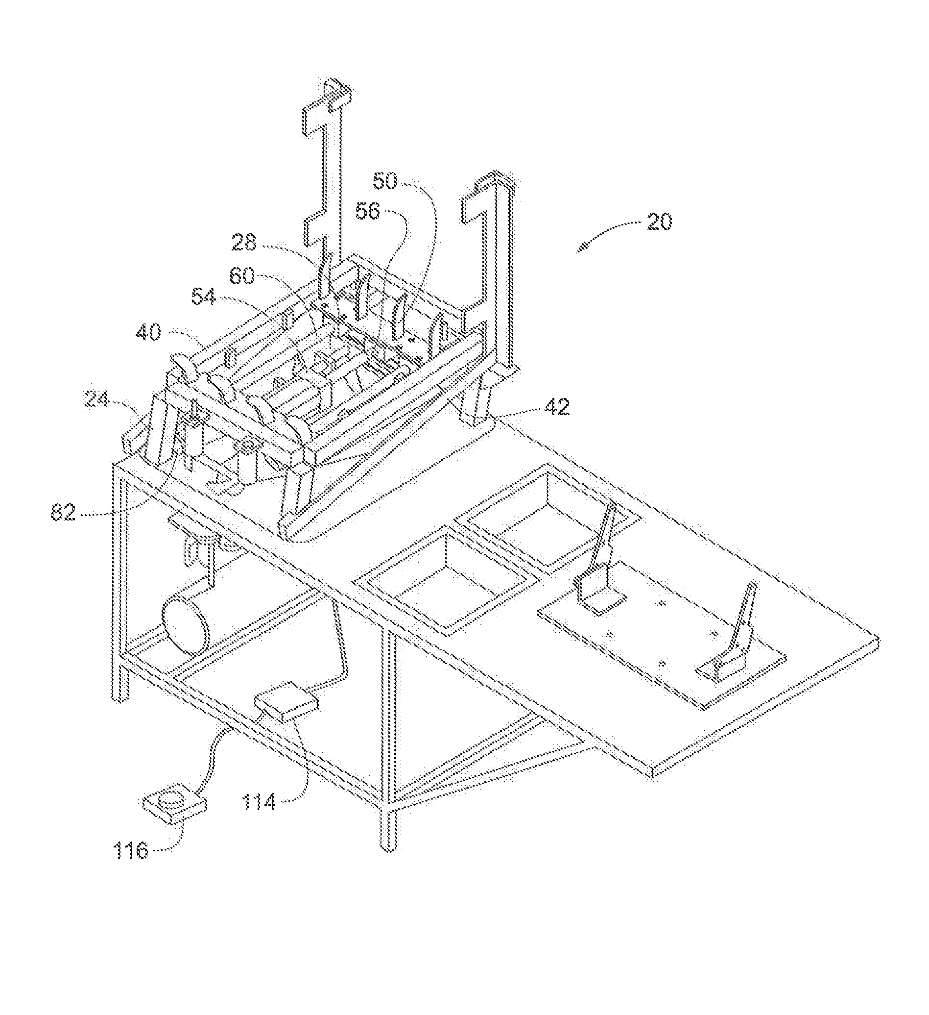
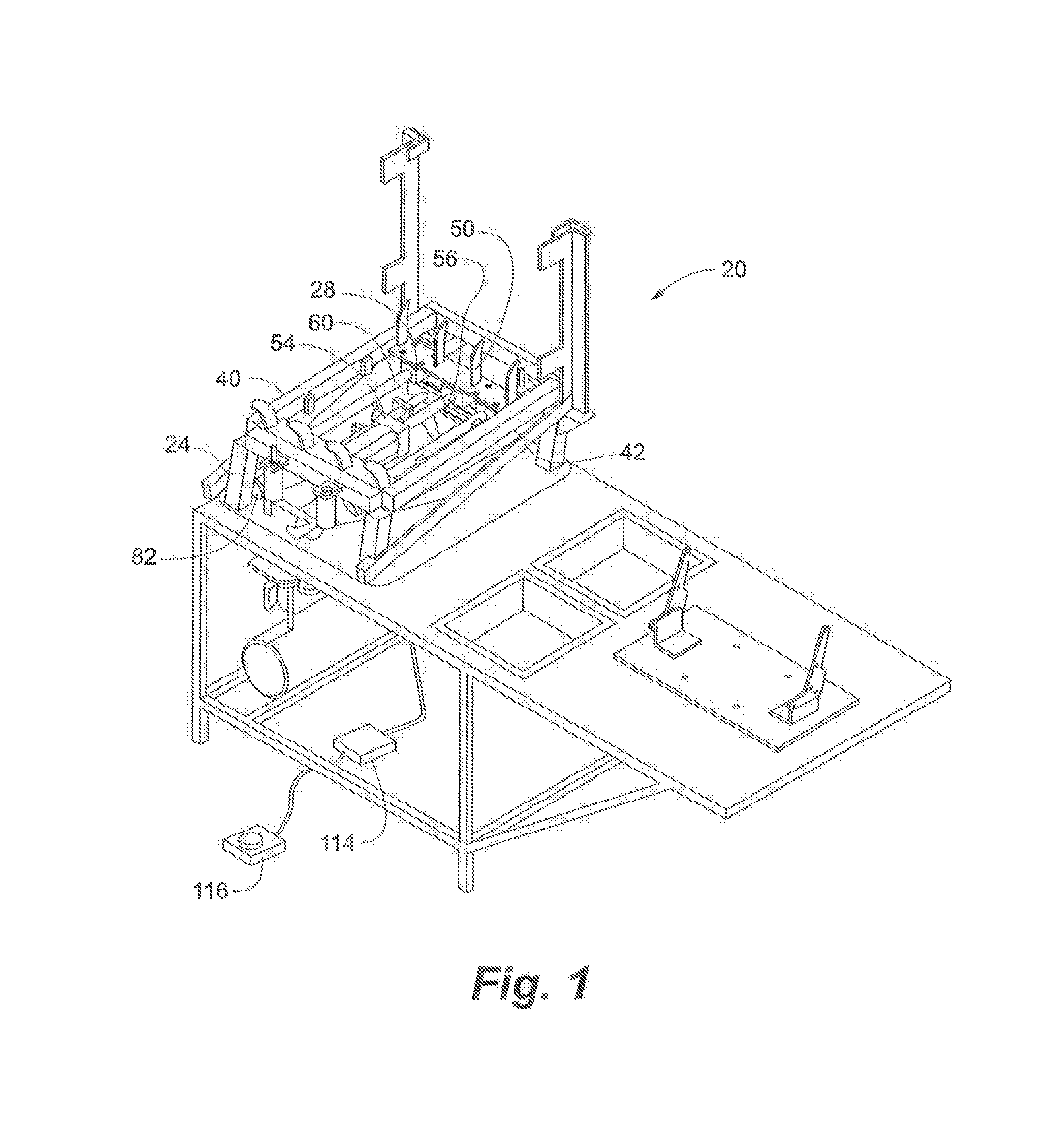
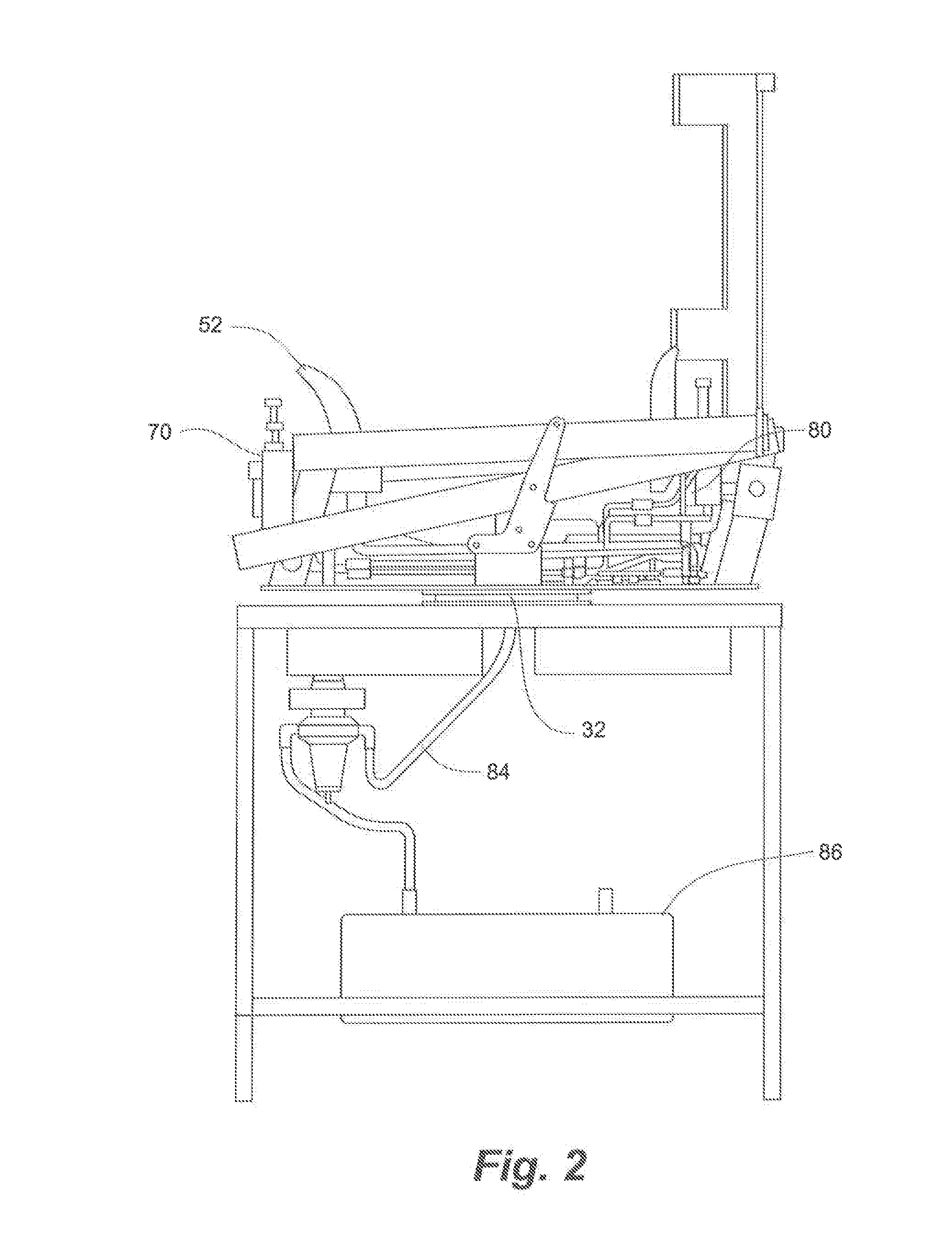
[0053]As depicted in FIGS. 1-6, a furniture assembly jig 20, according to an embodiment of the present invention, comprises a jig frame 24, a furniture frame member positioning portion 25 and a spring stretcher portion 28. Generally, the jig frame 24 is adapted to receive and position a plurality of frame components for a seat box. The jig frame 24 can position the frame components at the proper spacing and orientation for receiving fasteners to assemble the seat box or attaching other furniture components for the furniture item. Similarly, the spring stretcher portion 28 is adapted to receive at least one axially stretchable spring and apply an axial force to the spring to stretch the string to a predetermined tension. The spring can comprise coiled springs, s-shaped springs, interconnected spring webbing and other conventional springs or elastic structures that are attached to furniture seat boxes for providing a flexible seating surface. The spring stretcher portion 28 also posit...


PUM

PropertyMeasurementUnit
Distanceaaaaaaaaaa

Abstract

A furniture jig comprises a frame member positioning portion and a spring stretcher portion with at least the positioning frame portion having a rotating feature. The positioning frame portion may surround the spring stretcher portion and comprises constraint members that define receiving regions, such as slots or channels, into which furniture components, such a box frame members, may be inserted. The receiving regions of the jig frame maintain the furniture components upright or in other useful orientations at least until they are affixed together. In embodiments, the spring stretcher has a plurality of spring receiving portions on which the ends of a spring can be releasably engaged. Support members extending from the spring receiving portions operate to move the spring receiving portions from a spring loading position in which the springs can positioned on the tips to a spring attachment position where the springs are securable to the frame members. Drive portions, such as pneumatic or hydraulic cylinders move the spring receiving portions and support members between the respective positions. A control processer can automate the motions and be activated by a pedal or other switch.

Description

RELATED APPLICATION[0001]The present application claims the benefit of U.S. Provisional Application No. 61 / 586,689, entitled FURNITURE ASSEMBLY JIG and filed Jan. 13, 2012, and U.S. Provisional Application No. 61 / 591,829, entitled SEAT WITH ELASTOMERIC SUSPENSION WEBBING AND METHODS OF MANUFACTURE and filed Jan. 27, 2012, which are incorporated herein in its entirety.FIELD OF THE INVENTION[0002]The present invention is generally directed to a furniture assembly jig for positioning furniture components for attachment of fasteners and other components in the assembly of a furniture item. Specifically, the present invention is directed to a furniture jig for tensioning and positioning springs or an elastomeric suspension webbing on frame components for securing the springs to the frame components in the assembly of a furniture item having a flexible seating surface.BACKGROUND OF THE INVENTION[0003]A conventional chair or sofa typically comprises a rectangular frame or “seat box” having...

Claims


Application Information

Patent Timeline
IPC IPC(8): B25B11/02
CPCB25H1/10B25H1/14B25B11/02Y10T29/53961Y10T29/49863
Inventor GREEN, JEFFERY C.LEJCHER, CHRISTOPHER JONBRANDTNER, TIMOTHY A.
Owner ASHLEY FURNITURE IND INC
Why Eureka
Try Eureka