Electromagnetic switching device

a switching device and electromagnetic technology, applied in the field can solve the problems of limiting the miniaturization of electromagnetic switching devices, difficult to miniaturize electromagnetic switching devices, etc., and achieve the effect of reducing the vibration of electromagnetic switching devices and quieting the operating nois

Inactive Publication Date: 2007-01-02
MATSUSHITA ELECTRIC WORKS LTD
View PDF15 Cites 49 Cited by
  • Summary
  • Abstract
  • Description
  • Claims
  • Application Information

AI Technical Summary

Benefits of technology

[0017]With this type of mechanism, because the quasi-hermetically sealed space is formed by the enclosing component and at least the first yoke, and the movable contact points and the fixed contact points are placed in the quasi-hermetically sealed space, it is possible to miniaturize the extinguishing space and to maintain the extinction performance. Thus, it becomes possible to miniaturize the electromagnetic switching device. In other words, it is possible to increase the capability to cool off the arc (to absorb the energy) because metals have good heat conductance compared to molding materials (resin). In this regard, because the first yoke made of metals is used as a constructional component for the quasi-hermetically sealed space, the extinction performance improves and rapid blocking of the contact points becomes possible. Also, it is possible to share the components of the electromagnetic switching device and to miniaturize, thereby reducing the cost by reducing the number of components of the electromagnetic switching device. Because extinguishing space is constituted within the quasi-hermetically sealed space, the arc does not leak to the outside of this space or damage the solenoid coil of the electromagnetic switching device, and it is possible to maintain the insulation performance between the circuit side that is opened and closed (the primary side) and the controlling side of the electromagnetic switching device (the secondary side.)
[0018]In the improved invention described above, it is preferable that this invention has a body that holds the main body of the electromagnetic switching device with said terminal area projected outward, and that the space between said body and said quasi-hermetically sealed space is filled with a potting compound. With this type of mechanism, because the potting compound is charged into the space between the body and the quasi-hermetically sealed space, it is possible to quickly cool down the constructional components of the quasi-hermitically sealed space (the enclosing component and at least the first yoke) that are heated by the arc generated between the contact points. This can be done by using a compound that has good heat conductance as a potting compound. Therefore, it is possible to block the arc by quickly absorbing the heat energy of the arc. Also, because the potting compound restrains the propagation of the vibration that occurs from the inside of the main body of the electromagnetic switching device to the body, a silencing effect can be obtained. By using the potting compound, a covering component is not needed and the body can be built with only one component. This enables the lowering of costs.
[0019]In the improved invention described above, it is preferable that the distance between an inside wall of said enclosing component and said movable contact is narrow at the part that is near said shaft, and is wider at the part that is far from said shaft. With this type of mechanism, because the distance between the inside wall of the enclosing component and the movable contact is narrow at the part that is near the shaft and is wider at the part that is far from the shaft, it is possible to restrain the rotational position change of the movable contact caused by the spinning of the shaft that fixes the center part of the movable contact. Thus, the contact position of the movable contact points against the fixed contact points can be stable and the current control by the electromagnetic switching device can be performed more stably.
[0027]With this type of mechanism, it is possible to restrain the vibration of the electromagnetic switching device from transmitting to outside and to make an operating noise quiet.

Problems solved by technology

However, because the existing electromagnetic switching devices mentioned above have space (extinguishing space SP) to scatter the energy of the arc by stretching the arc spatially for the purpose of quickly extinguishing the arc generated at the time of opening and closing of the circuit, there is a problem that it is difficult to miniaturize the electromagnetic switching devices.
In addition, the arc is occasionally brought into contact with the resin of the body 11 to generate an extinguishing gas, and in this case, because it is necessary to enclose the extinguishing space with the resinous component that generates the extinguishing gas, there is a limit in miniaturizing the electromagnetic switching device.

Method used


Image

  • Electromagnetic switching device
  • Electromagnetic switching device
  • Electromagnetic switching device

Examples


embodiment 1

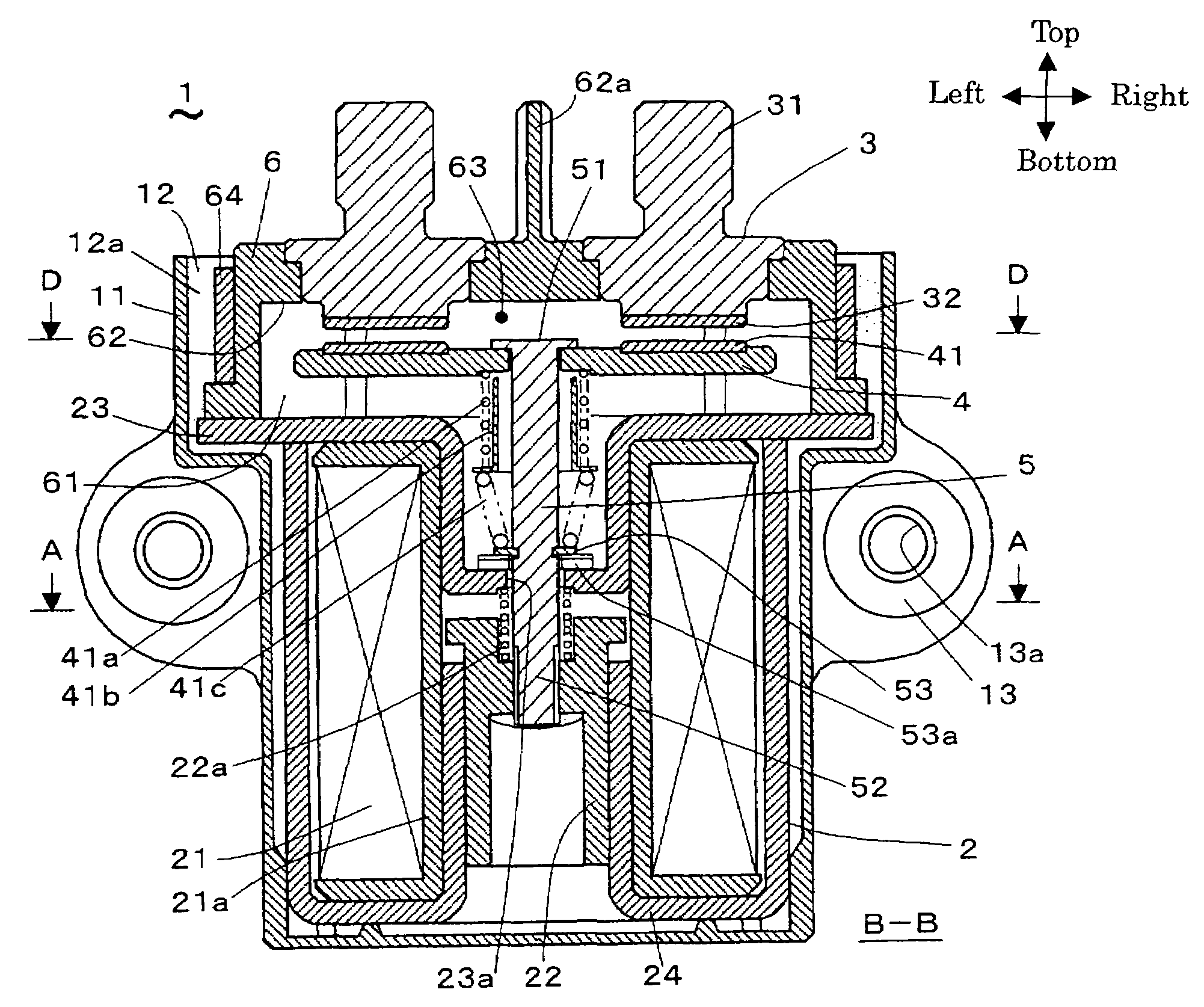
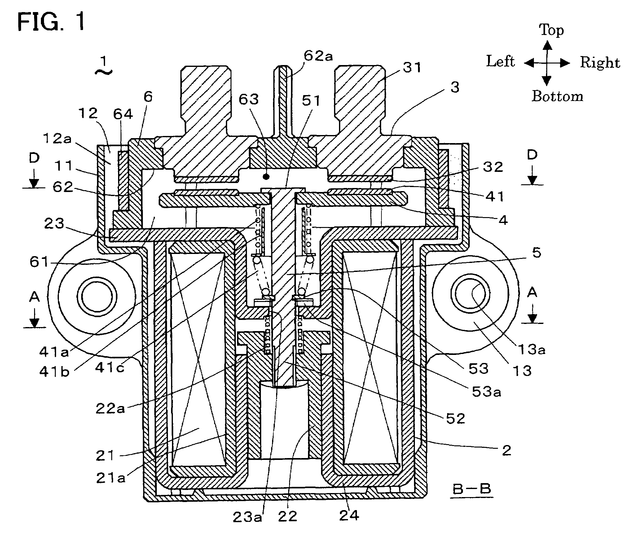
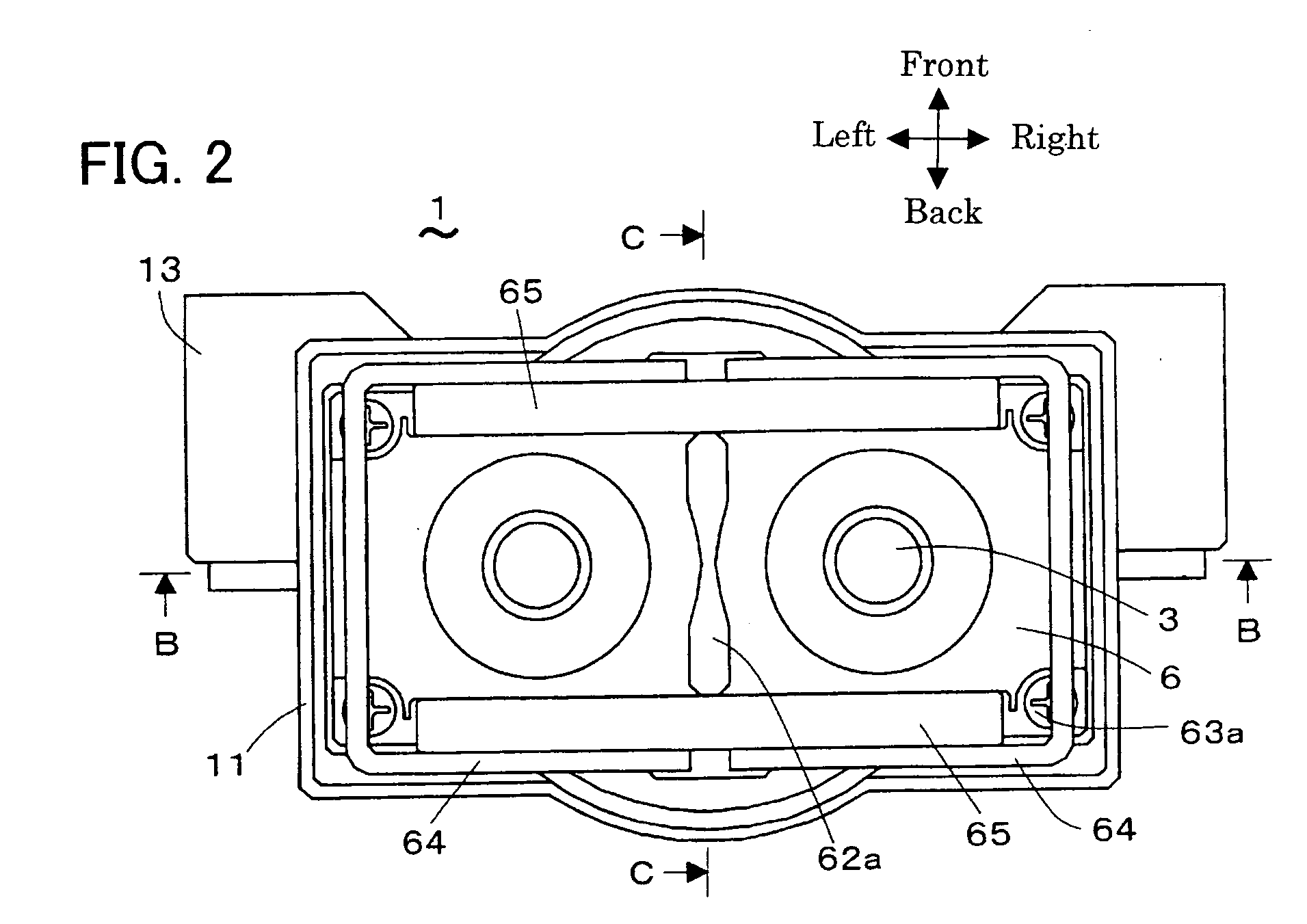
[0050]FIGS. 1 to 8 show the electromagnetic switching device of Embodiment 1. FIG. 1 is mainly referred to and the other figures are referred to accordingly as below. The electromagnetic switching device 1, as shown in FIG. 1, has the electromagnetic actuator 2 that has the movable iron core 22, the pair of fixed terminals 3 that respectively has the fixed contact points 32, the movable contact 4 that has the movable contact points 41 on the right and left ends, the shaft 5, and the enclosing component 6 that holds the movable contact points 41 and the fixed contact points 32. The pair of movable contact points 41 respectively contact with and detach from the pair of fixed contact points 32, and the pair of fixed contact points 32 are each respectively conducted by each other or insulated again through the shaft 5 by the electromagnetic actuator 2 moving the movable iron core 22 along the axis (hereafter referred to as the direction of up and down or the axis that is placed vertical...

embodiment 2

[0067]FIGS. 9 and 10 show the electromagnetic switching device 1 in Embodiment 2. This electromagnetic switching device 1 has a recess 8 with an insertion hole 81 facing downward at the center of the bottom part 62 of the enclosing component 6, and the point that the upper part of the shaft 5 is inserted and closes the inserting hole 81 is different form the electromagnetic switching device 1 in Embodiment 1 (for instance, refer to FIG. 1.) When the top part of the shaft 5 moves up and down, gas, fluids or particles that become resistant to the up and down movement of the shaft fill the recess 8.

[0068]In Embodiment 2 of this mechanism, it is possible to reduce the impact given when the movable contact points 41 contact with and detach from the fixed contact points 32 by the resistance of the gas, fluids or particles to the movement of the shaft 5, and to reduce the operating noise of the electromagnetic switching device 1. Additionally, because the resistance of the gas, fluids or p...

embodiment 3

[0070]FIG. 11 shows the recess 8 of the electromagnetic switching device 1 in Embodiment 3. The electromagnetic switching device of Embodiment 3 forms the flange 54, which rubs upward and downward along the inner surface of the recess 8, on the upper end of the shaft 5, and it has a valve 58 that opens and closes the insertion hole 57 over the flange 54 as well as the insertion hole 57 on the flange 54, and the upper end of the shaft 5 including the flange 54 is inserted into the insertion hole 81 and closes the insertion hole 81, and the gas, fluids or the particles that become resistant to the movement of the shaft 5 along the axis placed vertically.

[0071]In Embodiment 7 of the mechanism mentioned above, when the shaft 5 moves upward, it is possible to reduce the moving speed of the movable contact 4 because of the resistance of the gas, fluids or the particles in the recess 8. On the other hand, when the shaft 5 moves downward, it is not possible to slow down the moving speed of ...


PUM


Abstract

In the electromagnetic switching device, it is possible to miniaturize and have low costs, have quiet operation noise, and also quickly extinguish the arc. The electromagnetic switching device has an electromagnetic actuator with a movable iron core, a pair of fixed terminals that respectively have a fixed contact point, a movable contact that has movable contact points on the right and left ends, a shaft, and an enclosing component that holds the movable contact points and the fixed contact points. The pair of movable contact points respectively contact with and detach from the pair of fixed contact points, and the pair of fixed contact points respectively conduct each other and are insulated again through the shaft by moving the movable iron core along the axis using the electric magnetic actuator. A quasi-hermetically sealed space, which is the extinguishing space, is formed by the enclosing component and a first yoke. A potting compound is charged, into the space between a body and the quasi hermitically sealed space.

Description

FIELD OF THE INVENTION[0001]The present invention relates to an electromagnetic switching device to make or break a circuit in an electric drive mobile object e.g.BACKGROUND OF THE INVENTION[0002]Conventionally, in electromagnetic switching devices, some of them have been used for the purpose of making and breaking an electric power circuit of a vehicle, using the format whereby the contact mechanism is operated by opening and closing with an electromagnetic actuator. As examples of these types of electromagnetic switching devices, the ones shown in FIGS. 19, 20 and 21 are well known. These types of examples include the Japanese Patent Laid-Open Publication No. 2002-42628.[0003]This electromagnetic switching device consists of a body 11 made of resin (plastic), an electromagnetic actuator 2, a pair of fixed terminals 3, a movable contact 4, a shaft 5, etc. as shown in the Figure.[0004]The body 11 is formed into a box shape that is cut in half, and the main body of the electromagneti...

Claims


Application Information

Patent Timeline
Patent Type & Authority Patents(United States)
IPC IPC(8): H01H67/02H01H50/30H01H50/02H01H50/04
CPCH01H50/02H01H2009/0278H01H50/30H01H50/04
Inventor ENOMOTO, HIDEKIUOTOME, RIICHIYOKOYAMA, KOUJIKAMIOKA, KATSUYOSHI
Owner MATSUSHITA ELECTRIC WORKS LTD
Why Eureka
Try Eureka