Clock data recovery method and circuit for network communication

a network communication and clock technology, applied in the field of computer network communications, can solve the problems of generating high switching noise, unable to use different linear phase detectors, and prone to harmonic lockout in data streams, so as to reduce the risk of cdr, reduce the risk of pll output jitter, and consume less power

Inactive Publication Date: 2007-01-02
RPX CORP
View PDF14 Cites 11 Cited by
  • Summary
  • Abstract
  • Description
  • Claims
  • Application Information

AI Technical Summary

Benefits of technology

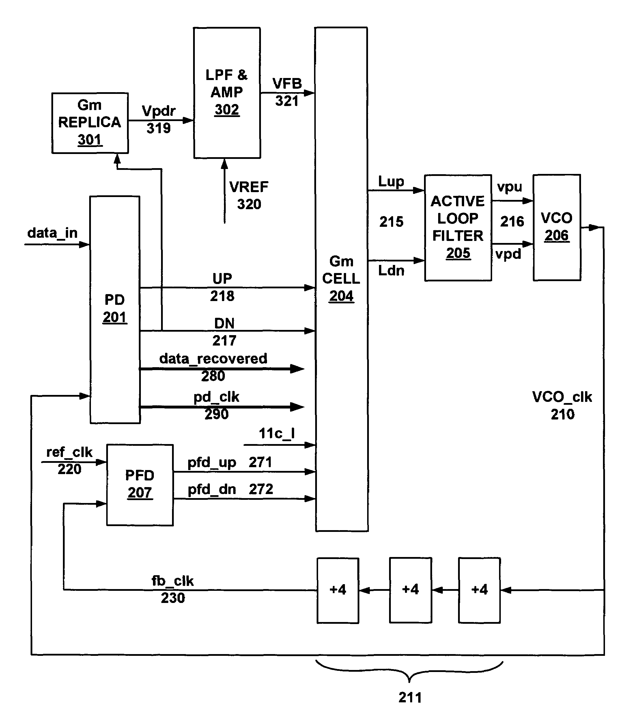
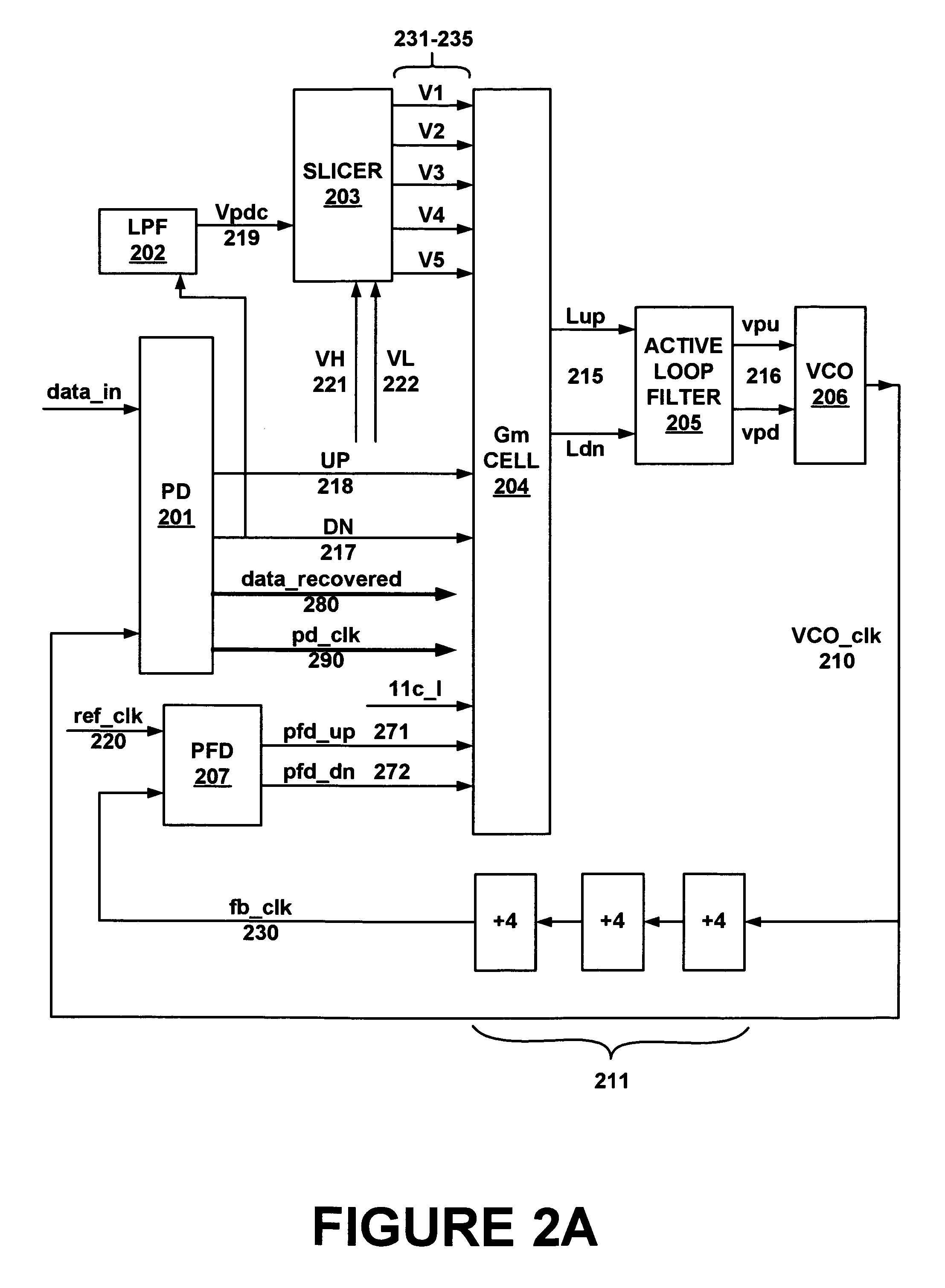
[0010]Accordingly, embodiments of the present invention are directed to a method and electronic system by which Clock and Data can be efficiently and reliably recovered. The method uses a novel technique of employing both data transition frequency detection and data transition phase detection to make for very reliable, accurate and low noise data reception.
[0012]By using the method presented in this embodiment of the present invention, CDR loop stability is improved. A direct benefit is jitter performance. The embodiment presents compensation in loop gain for input data transition density (DTD) variation. Therefore, loop stability is improved across various data transition density. The present invention allows a CDR loop to be used across various voltage-controlled oscillator (VCO) frequency rates, such as full rate and half rate.
[0014]The methods presented in the embodiments of the present invention discussed herein reduce the risk of a CDR from locking onto a wrong frequency in the data stream. Further, by updating Gm cell tail currents slowly and by responding to average data transition density through a low pass filter, jitter in the PLL output is reduced. Lower speed circuits generally consume less power and provide lower switching noise in Gm cells. Lower noise implies better jitter performance.

Problems solved by technology

In a typical Phase-Locked Loop (PLL) CDR design, it is difficult to have Clock and Data Recovery meet the Synchronous Optical Network (SONET) jitter transfer specification with 20 times DTD, especially in light of variations in process, supply voltage and temperature, or PVT.
However, schemes such as that described in the cited patent cannot used with different linear phase detectors and are prone to lock into harmonics in the data stream.
Further, they are necessarily higher speed devices and can generate high switching noise, implying high jitter, as well as consume higher power.

Method used


Image

  • Clock data recovery method and circuit for network communication
  • Clock data recovery method and circuit for network communication
  • Clock data recovery method and circuit for network communication

Examples


Embodiment Construction

[0026]Reference will now be made in detail to the preferred embodiments of the invention, examples of which are illustrated in the accompanying drawings. While the invention will be described in conjunction with the preferred embodiments, it will be understood that they are not intended to limit the invention to these embodiments. On the contrary, the invention is intended to cover alternatives, modifications and equivalents, which may be included within the spirit and scope of the invention as defined by the appended claims. Furthermore, in the following detailed description of the present invention, numerous specific details are set forth in order to provide a thorough understanding of the present invention. However, it should be understood by one of ordinary skill in the art that the present invention may be practiced without these specific details. In other instances, well-known methods, procedures, components, and circuits have not been described in detail so as not to unnecess...


PUM


Abstract

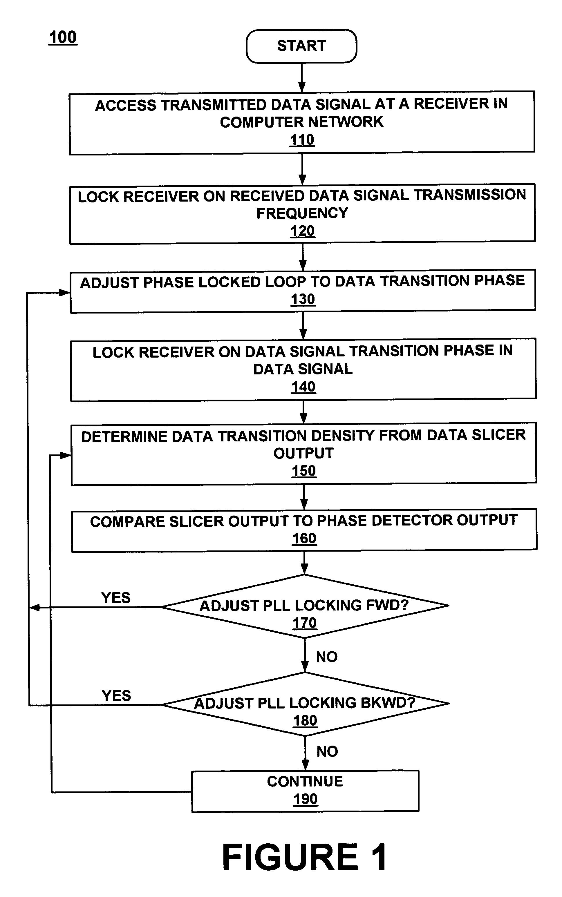
Embodiments of the present invention relate to a method for recovering the clock and data signals in a transmitted data signal In a computer network. The method comprises accessing a transmitted a data signal at a receiver in the network, locking the receiver on a data signal transmission frequency, then locking the receiver on a data signal transition phase in the transmitted data signal and adjusting the signal transition phase locking by reference to the transition density of the transmitted data signal. Embodiments adjust the transition phase locking by adjusting the tail current of a Gm cell in a phase locked loop in the receiver, based on the received data signal transition density.

Description

FIELD OF THE INVENTION[0001]Embodiments of the present invention relate to the field of computer network communications.BACKGROUND OF THE INVENTION[0002]Modern computer networks can communicate at very high data rates. Local Area Networks (LAN) and Wide Area Network (WAN) can transmit and receive hundreds of millions of bits per second over a single cable. Optically linked networks can communicate far faster, taxing the abilities of the even fastest processors.[0003]Maintaining accurate reception of signals transmitted in high speed networks requires that extremely accurate clocks be in synchrony at each end of a communication. Because different transmitters and receivers are located at different distances away from each other, and the amount of time to travel any length of cable varies, received data clock “ticks' can drift away from a receiver's clock. Hence, clock signals are necessarily inherent in data signals.[0004]Data transmission densities, the bit rates that are transmitte...

Claims


Application Information

Patent Timeline
Patent Type & Authority Patents(United States)
IPC IPC(8): H03D3/24H04L23/00
CPCH03L7/087H04L7/033H03L7/14
Inventor CHEW, CHWEI-PO
Owner RPX CORP
Why Eureka
Try Eureka