Fuel feed apparatus having opening in sub-tank

a fuel feed and sub-tank technology, which is applied in the direction of liquid fuel feeders, machines/engines, transportation and packaging, etc., can solve the problems of deterioration of remaining fuel, corrosion of components of fuel feed apparatus such as the sub-tank, and inability to maintain the proper operation of components, so as to reduce the amount of remaining fuel

Inactive Publication Date: 2007-01-09
DENSO CORP
View PDF8 Cites 6 Cited by
  • Summary
  • Abstract
  • Description
  • Claims
  • Application Information

AI Technical Summary

Benefits of technology

[0004]In view of the foregoing problems, it is an object of the present invention to produce a fuel feed apparatus that is capable of reducing fuel remaining in a sub-tank.

Problems solved by technology

However, fuel may remain in another chamber, in which the fuel pump is not provided, and the remaining fuel may be deteriorated due to oxidization.
As a result, components of the fuel feed apparatus such as the sub-tank may be corroded due to the deteriorated fuel, and proper operation of components may not be maintained.

Method used


Image

  • Fuel feed apparatus having opening in sub-tank
  • Fuel feed apparatus having opening in sub-tank
  • Fuel feed apparatus having opening in sub-tank

Examples


first embodiment

(First Embodiment)

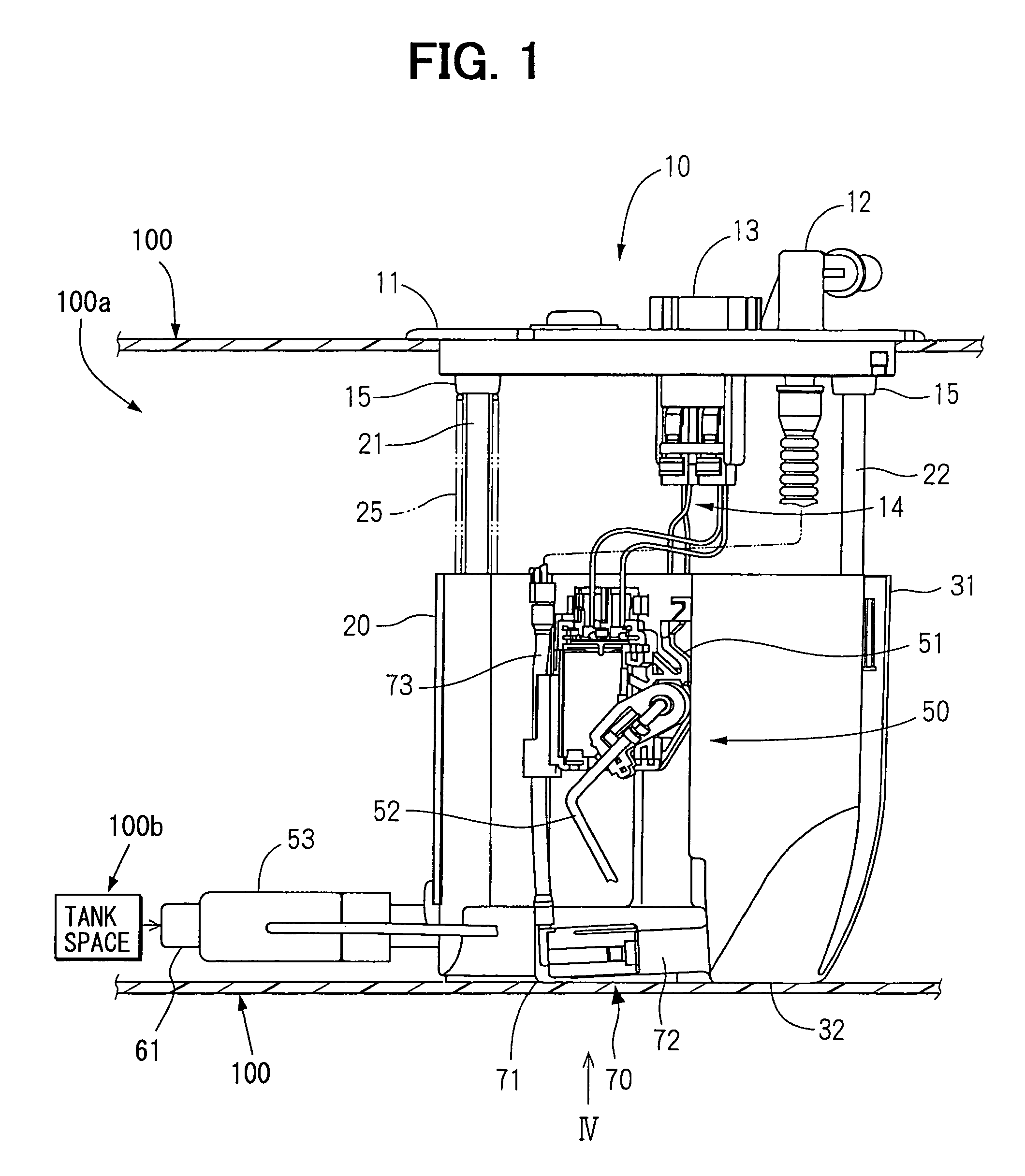
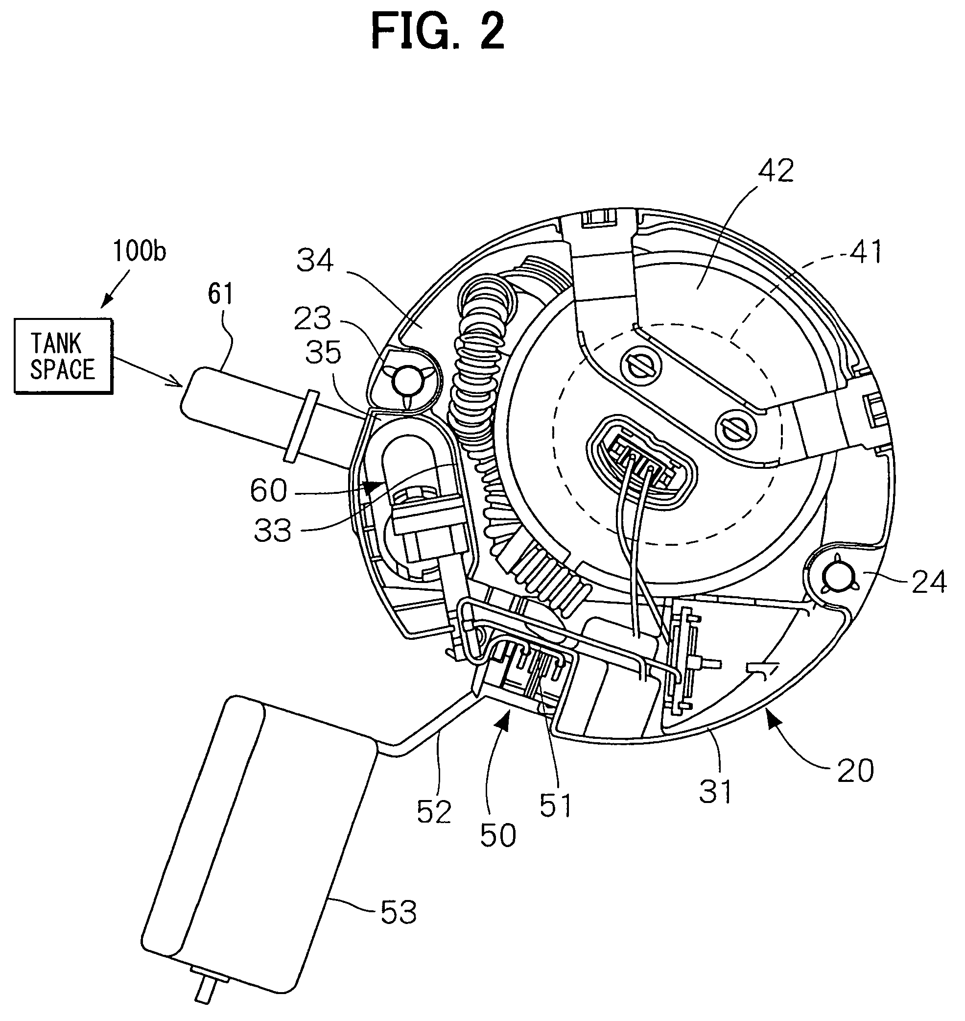
[0013]As shown in FIG. 1, a fuel feed apparatus 10 has a circular-shaped lid member 11 that covers an opening formed in an upper wall portion of a fuel tank 100. As shown in FIG. 6, the fuel tank 100, which receives the fuel feed apparatus 10, is integrally formed of resin to be in a saddleback shape, and is mounted in a vehicle over a drive shaft 200. The fuel tank 100 includes a first tank space 100a and a second tank space 100b that are communicated with each other through a connecting portion 100c, which is arranged to pass over the drive shaft 200. The fuel feed apparatus 10 is received in the first tank space 100a of the fuel tank 100.

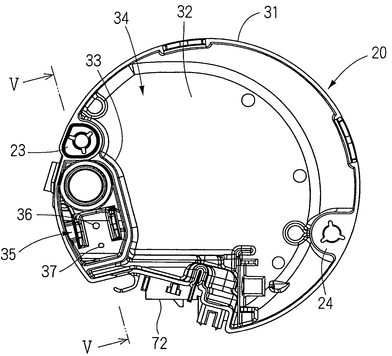
[0014]As shown in FIGS. 1, 2, the fuel feed apparatus 10 includes the lid member 11 and a sub-tank 20. The fuel feed apparatus 10 further includes a first shaft 21 and a second shaft 22 that support the lid member 11 and the sub-tank 20 such that the lid member 11 and the sub-tank 20 are axially movable relative to each other. M...


PUM


Abstract

A fuel feed apparatus includes a sub-tank and a fuel pump that are received in the fuel tank. The sub-tank has an inner space that is partitioned into at least a first chamber and a second chamber. The fuel pump is arranged in the first chamber to discharge fuel received in the sub-tank to the outside of the fuel tank. The second chamber has an opening, through which the second chamber communicates with the outside of the sub-tank such that fuel accumulated in the second chamber is exhausted to the outside of the sub-tank through the opening. The fuel tank has a first tank space and a second tank space. The sub-tank is received in the first tank space. A first jet pump is disposed in the second chamber of the sub-tank. The first jet pump draws fuel accumulated in the second tank space into the first tank space.

Description

CROSS REFERENCE TO RELATED APPLICATIONS[0001]This application is based on and incorporates herein by reference Japanese Patent Application No. 2004-23656 filed on Jan. 30, 2004.FIELD OF THE INVENTION[0002]The present invention relates to a fuel feed apparatus that feeds fuel received in a fuel tank to the outside of the fuel tank.BACKGROUND OF THE INVENTION[0003]A fuel feed apparatus disclosed in JP-A-9-268957 is capable of stably feeding fuel from an inside of a fuel tank to the outside, even when an amount of fuel received in the fuel tank decreases. The fuel feed apparatus includes a sub-tank that is received in the fuel tank. The inner space of the sub-tank needs to be partitioned into multiple chambers to individually receive components in the fuel feed apparatus having a specific structure. A fuel pump may be arranged in one of the separated chambers. In this structure, fuel can be circulated in the chamber receiving the fuel pump. However, fuel may remain in another chamber, ...

Claims


Application Information

Patent Timeline
Patent Type & Authority Patents(United States)
IPC IPC(8): F02M37/04B60K15/03F02M37/00F02M37/02F02M37/10F02M37/18
CPCF02M37/106F02M37/025Y10T137/86187Y10T137/86212
Inventor HAYASHI, NORIHIROOKAZONO, TETSURO
Owner DENSO CORP
Why Eureka
Try Eureka