Method for forming a resist pattern of magnetic device by etching with a gas cluster ion beam

a magnetic device and gas cluster technology, applied in nanoinformatics, instruments, record information storage, etc., can solve the problems of increasing the resistance density of the magnetic head manufactured by the conventional manufacturing method, the inability to maintain good electrical contact between the upper electrode and the non-magnetic metal layer, and the increase of the resistance density of the magnetic head. achieve the effect of increasing the recording density

Inactive Publication Date: 2010-08-31
TDK CORPARATION
View PDF23 Cites 3 Cited by
  • Summary
  • Abstract
  • Description
  • Claims
  • Application Information

AI Technical Summary

Benefits of technology

[0018]It is an object of the invention to provide a pattern forming method which is capable of removing or reducing unwanted products remaining on a peripheral region of a film which is patterned by dry etching using a resist pattern for lift-off as a mask.
[0019]It is another object of the present invention to provide a method of manufacturing a magneto-resistive device, which is capable of reducing unwanted products remaining on a peripheral region of a film which is patterned by dry etching using a resist pattern for lift-off as a mask, to advantageously reduce a series resistance component and / or more effectively apply a vertical bias to a free layer.
[0020]It is still another object of the present invention to provide a method of manufacturing a magnetic head, which can provide the same advantages as above.

Problems solved by technology

Thus, if another layer such as the upper electrode is formed on the non-magnetic metal layer as it is, a good electrical contact cannot be maintained between the upper electrode and the non-magnetic metal layer.
Thus, if other layers such as the lead layers are formed on the non-magnetic metal layer as it is, a good electrical contact cannot be maintained between the lead layers and the non-magnetic metal layer.
However, in the conventional manufacturing method for manufacturing the aforementioned CPP-based head and LOL-based head, the surface oxide film on the non-magnetic metal layer, redeposits produced during the dry etching such as ion milling, and the insulating layer (or the laminate of the insulating layer and metal layer (magnetic domain control layer)) remain on a peripheral region and the like of the non-magnetic metal layer due to the resist pattern for lift-off which has a shape at cross section including an undercut or an inverse tapered shape at cross section, thereby limiting a path for a current which flows into the magneto-resistive layer to reduce an area which has a good electrical contact.
As a result, the magnetic head manufactured by the conventional manufacturing method experiences an increase in a series resistance component of the magneto-resistive device, degraded MR characteristics, degraded frequency characteristics due to a higher resistance of the head, and the like.
It is difficult to reduce the dimensions of the undercut or the like of the resist pattern for lift-off to predetermined dimensions or less in order to avoid producing burrs and the like during the lift-off.
Thus, when a magneto-resistive device is reduced in size for increasing a recording density, the resulting magneto-resistive device has a significantly reduced area which makes an electrically good contact to strictly limit a path for a current which flows into a magneto-resistive layer, thereby notably affecting the magneto-resistive device due to the degraded MR characteristics, degraded frequency characteristics associated with a higher resistance of a head, and the like.
This results in a lower vertical biasing effect to the free layer by the magnetic domain control layer, thereby failing to sufficiently control the magnetic domains of the free layer.
Since it is difficult to reduce the dimensions of the undercut or the like of the resist pattern for lift-off to predetermined dimensions or less as mentioned above, a reduction in the dimensions of the magneto-resistive device for a higher recording density would significantly narrow down the distance between the piled portions of the magnetic domain control layers on both sides, thereby notably affecting the control for the magnetic domains of the free layer.
While a magnetic head manufacturing method has been given as an example for purposes of description, troubles can be also caused by the resist pattern for lift-off having the undercut or the like in a lift-off based pattern forming method which is used in a variety of applications other than the manufacturing of magnetic heads.
Specifically, troubles may be caused by unwanted products, which can be redeposits during ion milling, a second film formed around a first film, and the like, remaining on a peripheral region an the like of the first film patterned by ion milling or the like using the resist pattern for lift-off as a mask.

Method used


Image

  • Method for forming a resist pattern of magnetic device by etching with a gas cluster ion beam
  • Method for forming a resist pattern of magnetic device by etching with a gas cluster ion beam
  • Method for forming a resist pattern of magnetic device by etching with a gas cluster ion beam

Examples


first embodiment

[0120]First, a magnetic head manufactured by a magnetic head manufacturing method according to the present invention will be described with reference to FIGS. 1 to 5.

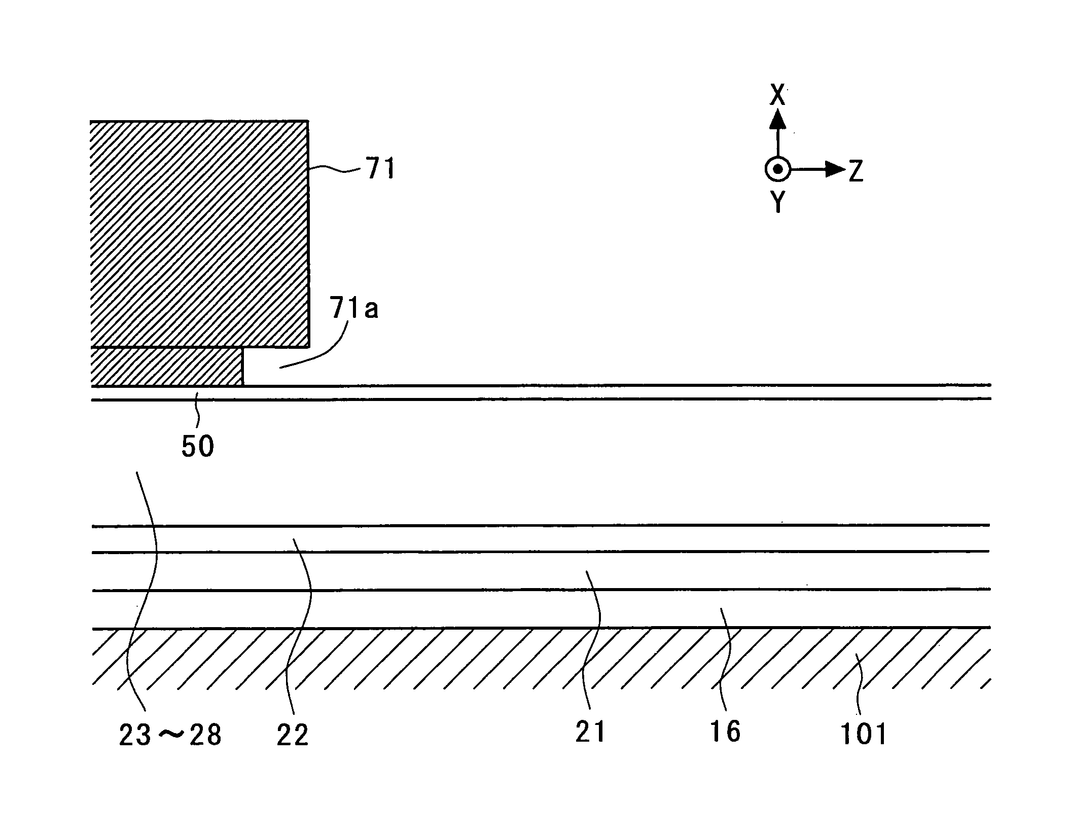
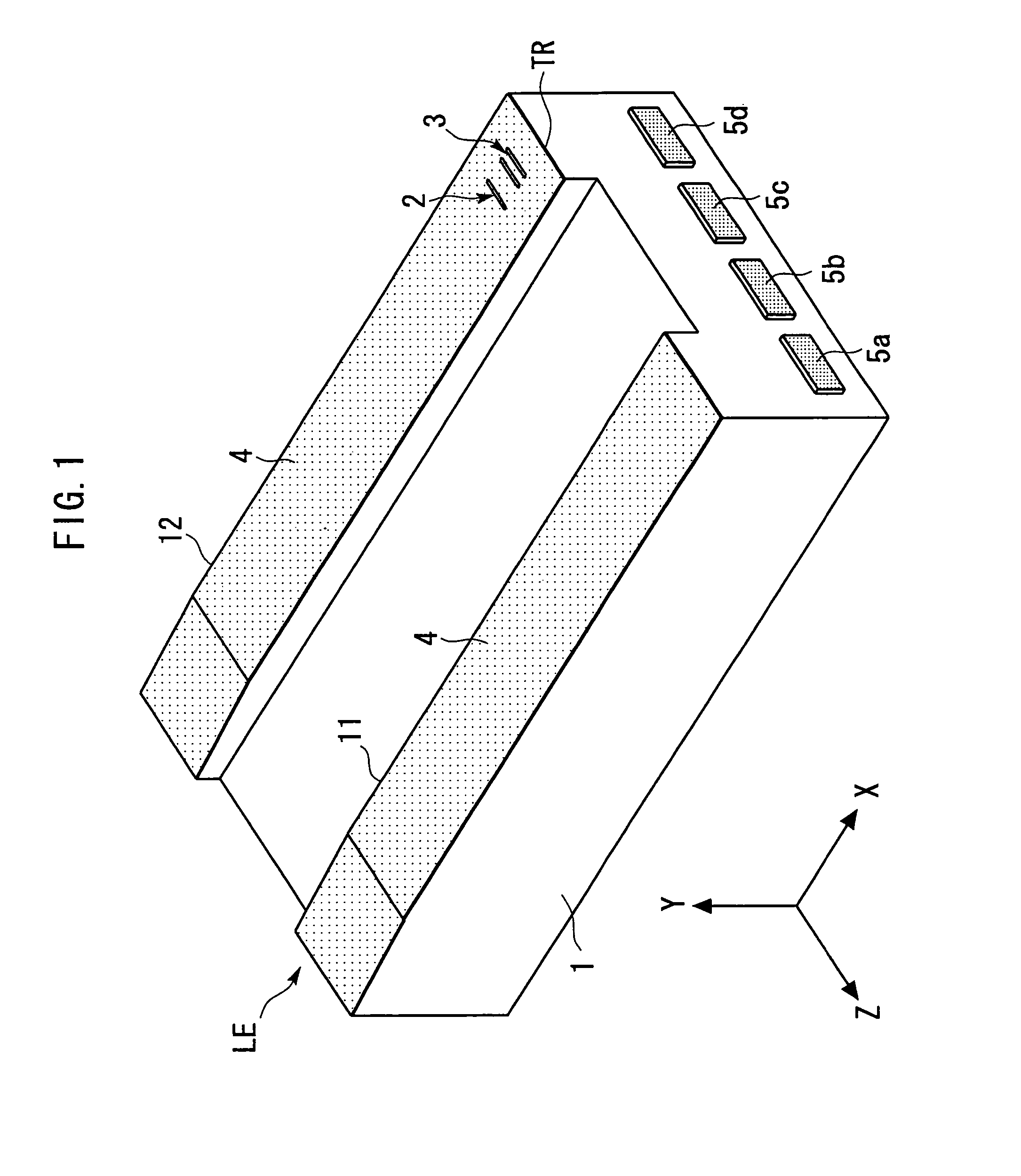
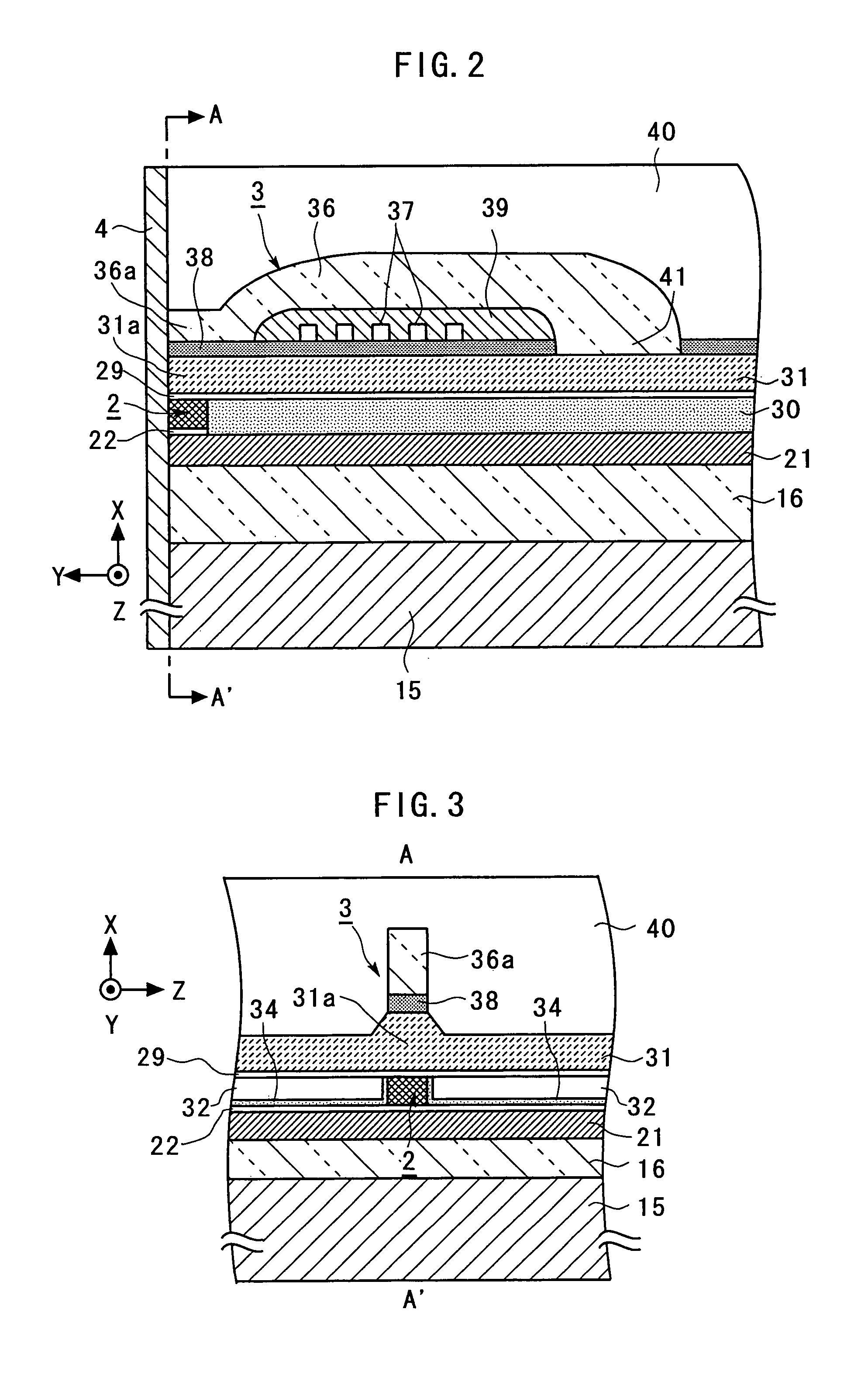
[0121]FIG. 1 is a general perspective view schematically illustrating the magnetic head manufactured by the magnetic head manufacturing method according to the first embodiment of the present invention. FIG. 2 is an enlarged cross-sectional view schematically illustrating a portion of a TMR device 2 and an inductive magnetic transducing device 3 in the magnetic head illustrated in FIG. 1. FIG. 3 is a general sectional view taken along a line A-A′ indicated by arrows in FIG. 2. FIG. 4 is a further enlarged view illustrating around the TMR device 2 in FIG. 2. FIG. 5 is a further enlarged view around the TMR device 2 in FIG. 3. For facilitating the understanding, an X-axis, a Y-axis and a Z-axis, orthogonal to one another, are defined as shown in FIGS. 1 to 5 (the same applies to figures later described). The Z-axis direct...

second embodiment

[0172]Next, a magnetic head manufacturing method according to the present invention will be described with reference to FIGS. 25 to 27.

[0173]FIG. 25 is an enlarged cross-sectional view schematically illustrating a portion of a TMR device 2 and an inductive magnetic transducing device 3 in a magnetic head manufactured by the magnetic head manufacturing method according to the second embodiment of the present invention. FIG. 26 is a further enlarged view around the TMR device 2 in FIG. 25. FIGS. 25 and 26 correspond to FIGS. 2 and 4, respectively. FIG. 27 is a cross-sectional view schematically illustrating a step in the magnetic head manufacturing method according to the second embodiment of the present invention, and corresponds to FIG. 17. In FIGS. 25 to 27, elements identical or corresponding to those of FIGS. 1 to 5 and FIG. 17 are designated by the same reference numerals, and repeated description thereon is omitted.

[0174]The magnetic head illustrated in FIGS. 25 and 26 differs ...

third embodiment

[0179]Next, a magnetic head manufacturing method according to the present invention will be described with reference to FIGS. 28 to 30.

[0180]FIG. 28 is an enlarged cross-sectional view schematically illustrating a portion of a GMR device 6 and an inductive magnetic transducing device 3 in a magnetic head manufactured by the magnetic head manufacturing method according to the third embodiment of the present invention. FIG. 29 is a further enlarged view around the GMR device 6 in FIG. 28. FIG. 30 is a general sectional view taken along a line B-B′ indicated by arrows in FIG. 29. FIGS. 28 to 30 correspond to FIGS. 2, 4 and 5, respectively. In FIGS. 28 to 30, elements identical or corresponding to those of FIGS. 1 to 5 are designated by the same reference numerals, and repeated description thereon is omitted.

[0181]The magnetic head illustrated in FIGS. 28 to 30 is an example of a magnetic head having the LOL structure. The magnetic head illustrated in FIGS. 28 to 30 differs from the mag...


PUM

PropertyMeasurementUnit
incident angleaaaaaaaaaa

Abstract

A resist pattern for lift-off is formed on a first film composed of one or more layers deposited on a substrate. The first film is patterned by dry-etching using the resist pattern as a mask. Subsequently, a second film is deposited with presence of the resist pattern on the first film. Then, the resist pattern for lift-off is removed for conducting lift-off. Subsequently, the resulting substrate is etched. In the etching, the substrate is dry-etched using etching particles which are oriented at an incident angle set in a range of 60 ° to 90 ° relative to the normal direction of the substrate.

Description

[0001]This is a Division of application Ser. No. 10 / 773,234, filed Feb. 9, 2004. The disclosure of the prior application is hereby incorporated by reference herein in its entirety.BACKGROUND OF THE INVENTION[0002]The present invention relates to a Method for Forming a Resist Pattern of Magnetic Device.[0003]With the trend to a larger capacity and a smaller size of hard disk drives (HDD), heads are required to have a higher sensitivity and a larger output. To meet these requirements, strenuous efforts have been made to improve the characteristics of GMR heads (Giant Magneto-Resistive Head) currently available on the market. On the other hand, intense development is under way for a tunnel magneto-resistive head (TMR head) which can be expected to have a resistance changing ratio twice or more higher than the GMR head.[0004]Generally, the GMR head differs from the TMR head in the head structure due to a difference in a direction in which a sense current is fed. A head structure adapted...

Claims


Application Information

Patent Timeline
Patent Type & Authority Patents(United States)
IPC IPC(8): G11B5/127C03C15/00G11B5/33C23F1/00G11B5/012G11B5/31G11B5/39H01L43/08H01L43/12
CPCB82Y10/00B82Y25/00G11B5/3903G11B5/3909G11B5/012G11B5/3116G11B5/3163Y10T29/49052G11B2005/3996Y10T29/49041Y10T29/4906Y10T29/49043Y10T29/49046Y10T29/49044
Inventor KAGAMI, TAKEOSATO, KAZUKI
Owner TDK CORPARATION
Why Eureka
Try Eureka