Radio frequency characterization of cable plant and corresponding calibration of communication equipment communicating via the cable plant

a technology of radio frequency characterization and cable plant, which is applied in the field of information cable plant employed in telecommunications, can solve the problems of limited data throughput capacity, insufficient existing legacy technology for providing broadband content, and limited spectrum available for delivery

Active Publication Date: 2007-01-09
ADVENT NETWORKS +1
View PDF18 Cites 135 Cited by
  • Summary
  • Abstract
  • Description
  • Claims
  • Application Information

AI Technical Summary

Problems solved by technology

The existing legacy technology for providing broadband content is becoming increasingly inadequate to meet the demand.
One problem with delivery of broadband data (video on demand, streaming video, etc.) using existing HFC networks is the limitation on available delivery spectrum.
DOCSIS systems use a shared frequency channel to broadcast all data to every downstream subscriber, and thus are limited in data throughput capacity.
Such methodology often significantly increased installation time and cost and the amount of equipment and human error in the field.
Furthermore, newer technologies require higher quality connections thereby increasing the problems associated with traditional installation methodology.
The problems were exacerbated since the intermediate network was, and still is, often owned by a separate entity from the owner or operator of cable equipment on either end, resulting in reduced control of the installation, troubleshooting and repair activities.
These problems were also compounded for older cable plants with significant variations, and unknown quality levels and characteristics.

Method used


Image

  • Radio frequency characterization of cable plant and corresponding calibration of communication equipment communicating via the cable plant
  • Radio frequency characterization of cable plant and corresponding calibration of communication equipment communicating via the cable plant
  • Radio frequency characterization of cable plant and corresponding calibration of communication equipment communicating via the cable plant

Examples


Embodiment Construction

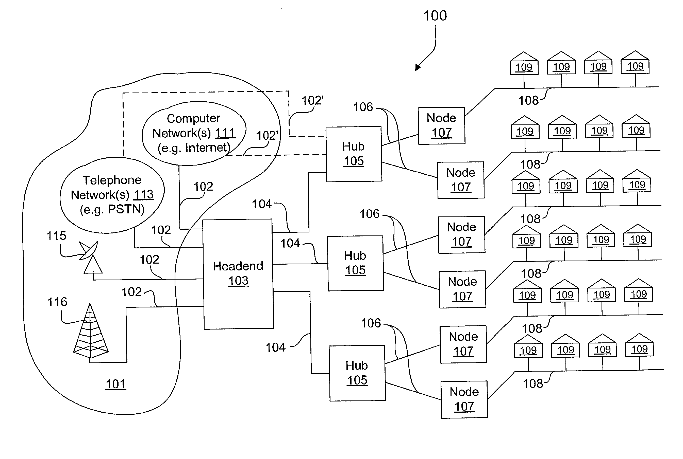
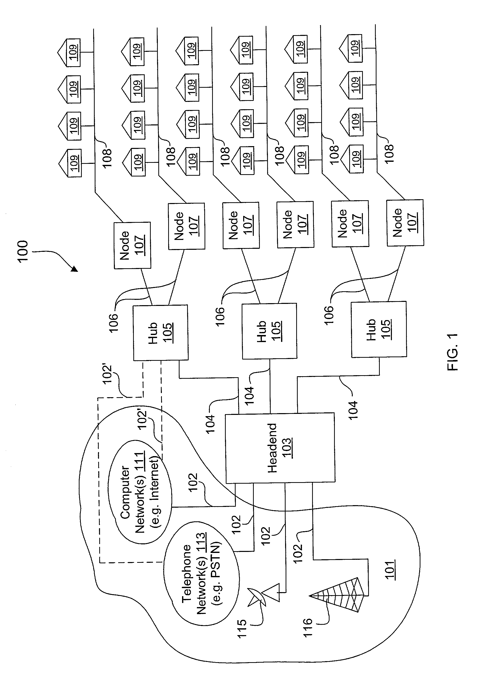
[0026]FIG. 1 is a block diagram of an exemplary communication system 100 with an exemplary network architecture. One or more sources 101 are coupled via appropriate communication links 102 to deliver source information to a headend 103, which distributes the source information to one or more distribution hubs 105 via respective communication links 104. Each distribution hub 105 further distributes source information to one or more nodes 107 via communication links 106, where each node 107 in turn distributes the source information to one or more subscriber locations 109 via subscriber links 108. In the embodiment shown, bi-directional communication is supported in which upstream subscriber information from any one or more of the subscriber locations 109 is delivered to the corresponding distribution hub 105 via the corresponding subscriber links 108. Depending upon the nature of the subscriber information and the network architecture, the subscriber information may be delivered to t...


PUM


Abstract

A switch router and one or more gateways incorporating a diagnostic and calibration system that performs RF characterization of an underlying cable plant. The switch router is connected at a point of insertion or point of distribution and each gateway is located downstream, such as at corresponding subscriber locations. The switch router and each gateway sends a test signal with known characteristics and power level, and the receiving device determines noise level and power loss for the corresponding downstream and upstream channel pair. The power loss information is used to calibrate the power level of the transmitters. The noise levels are used to determine if the selected modulation schemes employed for normal communications is realizable. A frequency analysis, such as FFT or the like, is performed on the upstream test signal spectrum to derive valuable frequency information for the upstream channel or the entire upstream bandwidth.

Description

FIELD OF THE INVENTION[0001]The present invention relates to information cable plants employed for telecommunications, and more particularly, to characterization of cable plants and calibration of associated communication equipment.DESCRIPTION OF RELATED ART[0002]The demand for broadband content by business and residential subscribers is continually increasing. Broadband content includes multiple types of entertainment programming, communications and data, such as broadcast television channels, video on demand, streaming video, multimedia data, internet access, voice-over-IP, etc. To meet the increasing demand, it is necessary to increase bandwidth to each subscriber and to improve quality of service. Existing delivery technologies include several variations of DSL (digital subscriber line) technology, such as ADSL (asymmetrical DSL) and the like, which uses telephony technology, cable modem systems using television technology and HFC (hybrid fiber coax) distribution networks, 2-way...

Claims


Application Information

Patent Timeline
Patent Type & Authority Patents(United States)
IPC IPC(8): H04N7/173H03G3/30H04L1/24H04L25/02H04L27/00H04L27/34
CPCH04L1/24H04N21/64723H04L27/34H04N7/17309H04N21/42676H04N21/615H04L27/0002H03G3/3036H04L25/022H04L25/0224H04L25/0226
Inventor REIDHEAD, LANCE R.EVANYK, WALT
Owner ADVENT NETWORKS
Why Eureka
Try Eureka