Fluid transfer system

a technology of fluid transfer and auxiliary gas can, which is applied in the direction of liquid fuel engines, liquid handling, packaging goods types, etc., can solve the problems of affecting so as to achieve the effect of reducing the risk of contamination, and reducing the efficiency of the engin

Active Publication Date: 2007-01-16
FRANKS NORMAL ALTON
View PDF4 Cites 18 Cited by
  • Summary
  • Abstract
  • Description
  • Claims
  • Application Information

AI Technical Summary

Benefits of technology

[0008]The instant invention comprises a fluid transfer apparatus that includes a jug-like container having a neck sealable by a cap member and a carrying handle. Affixed to the cap member is a rotary vane pump that has a first inlet / outlet port extending through the cap to an interior of the jug and a second inlet / outlet port exterior of the jug. A suction / discharge hose has a first end thereof connected to the second inlet / outlet port of the pump and a second end adapted for placement in a container for a liquid. A tether has one end thereof slidable along an exterior of the suction / discharge hose and a clamp member affixed to another end of the tether whereby the second end of the suction / discharge hose can be prevented from falling out of the container into or from which the liquid in the jug is to be transferred. Rotation of the vane pump in a first direction is effective to draw the liquid in the jug through the first inlet / outlet port and out the second inlet / outlet port and through the suction / discharge hose into the container or tank to be filled. By rotating the vane pump in the opposite direction, a liquid may be drawn from a supply container through the suction / discharge hose and the second inlet / outlet port and into the jug, via the first inlet / outlet port. The tether also serves to maintain the suction / discharge hose in the container to be filled or emptied at the same electrical potential such that static discharges are eliminated.

Problems solved by technology

This task becomes difficult where the entrance opening to the engine's fuel tank is relatively small in size or is at an angle to the horizontal or a difficult to reach location.
In an attempt to address the small size issue, the prior art solution has generally been to utilize a funnel, but this solution has its drawbacks.
Specifically, the rate at which the fuel can be poured from an auxiliary gas can into the engine's tank is limited by the build-up of a back pressure as the fuel displaces air in the engine's fuel tank.
Air can only escape back up through the opening in the funnel which not only produces harmful fumes, but also possible splattering of the fuel being poured.
With volatile fuels, such as gasoline, a potential exists for explosion or fire if static electric charge is able to build up on one or the other of the container transporting the fuel and the tank into which the fuel is to be deposited.
If the charge is sufficiently high, a spark can result that can ignite fumes resulting as the fuel is being poured into the engine's tank.

Method used


Image

  • Fluid transfer system
  • Fluid transfer system
  • Fluid transfer system

Examples


Embodiment Construction

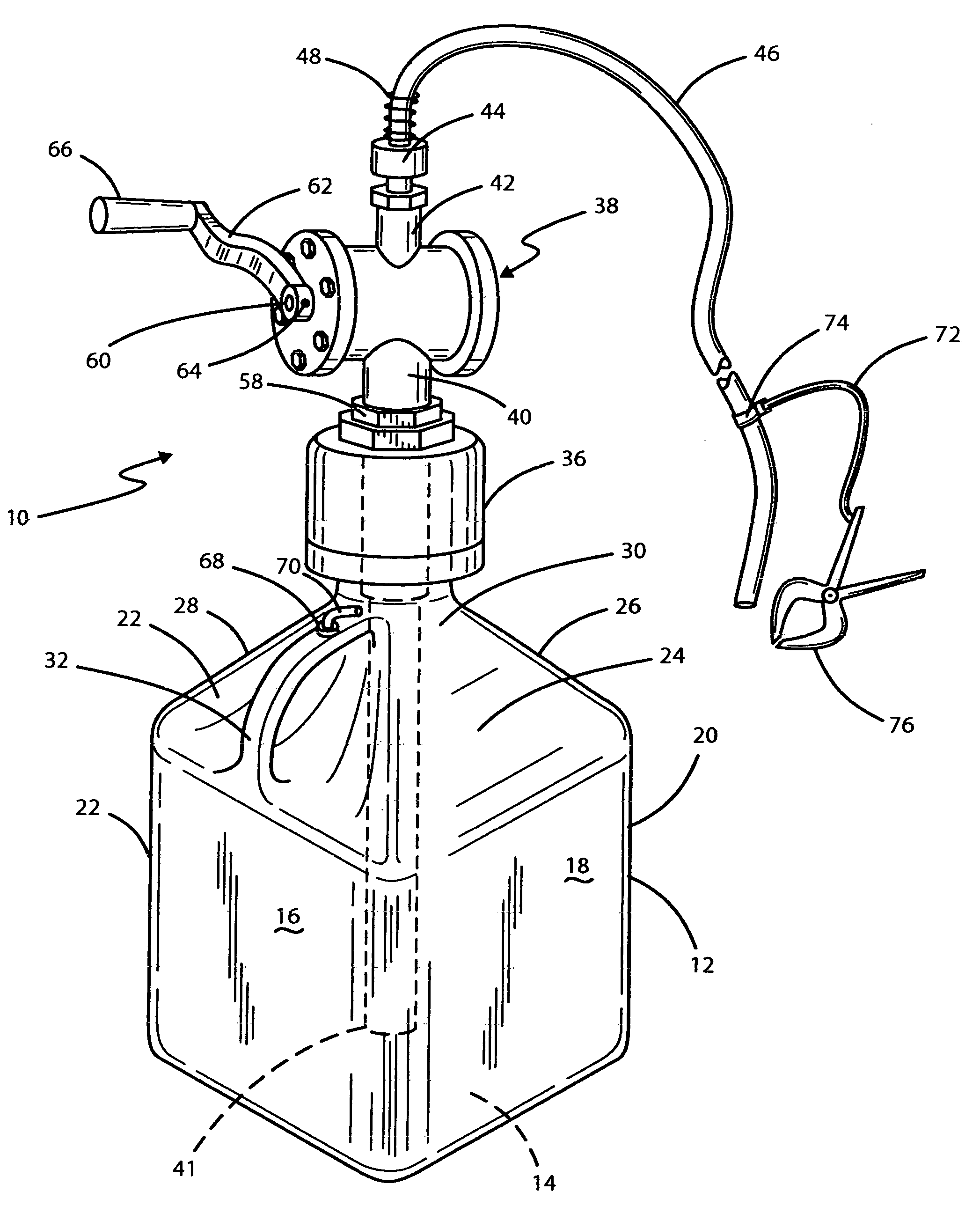
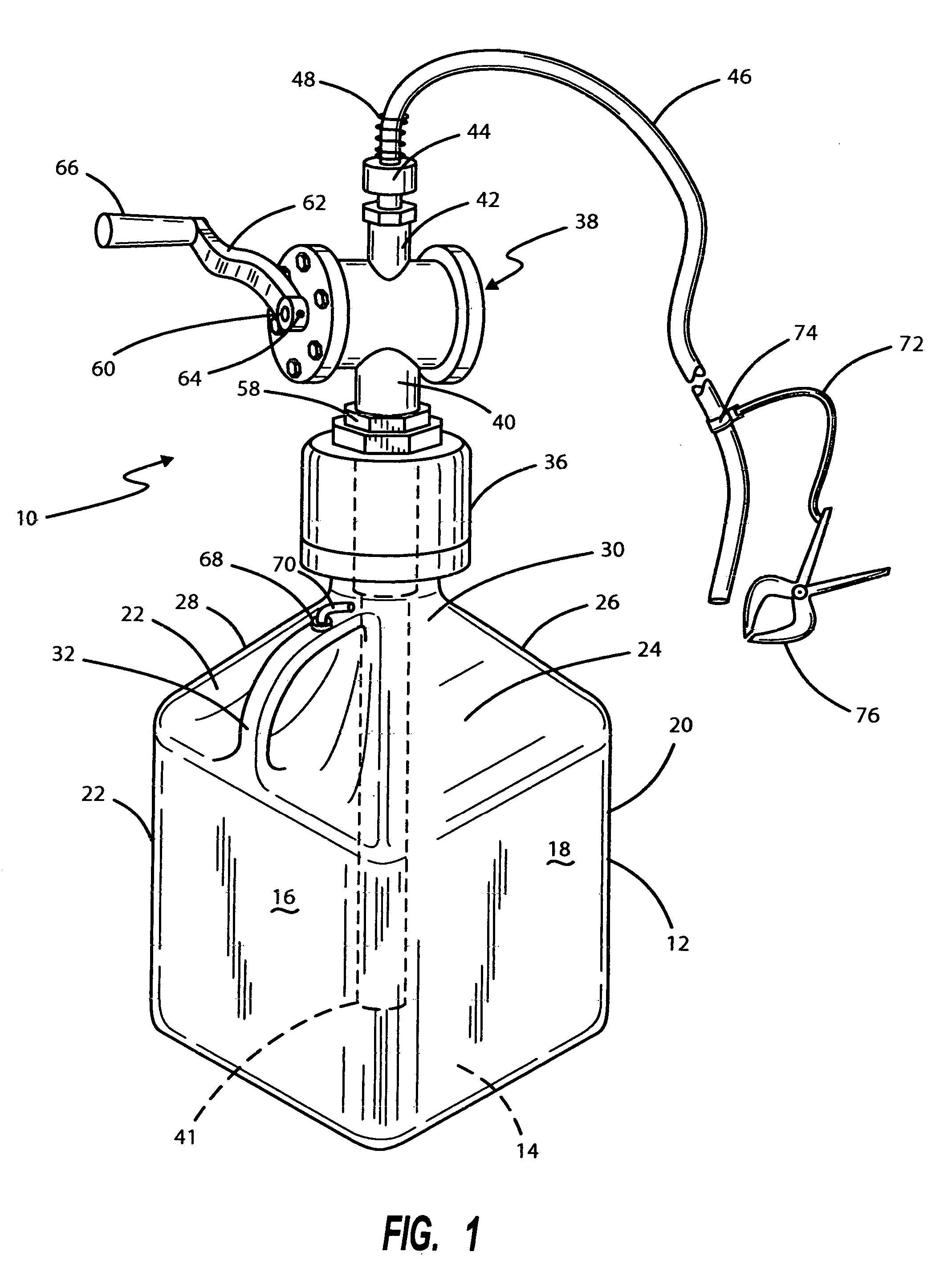
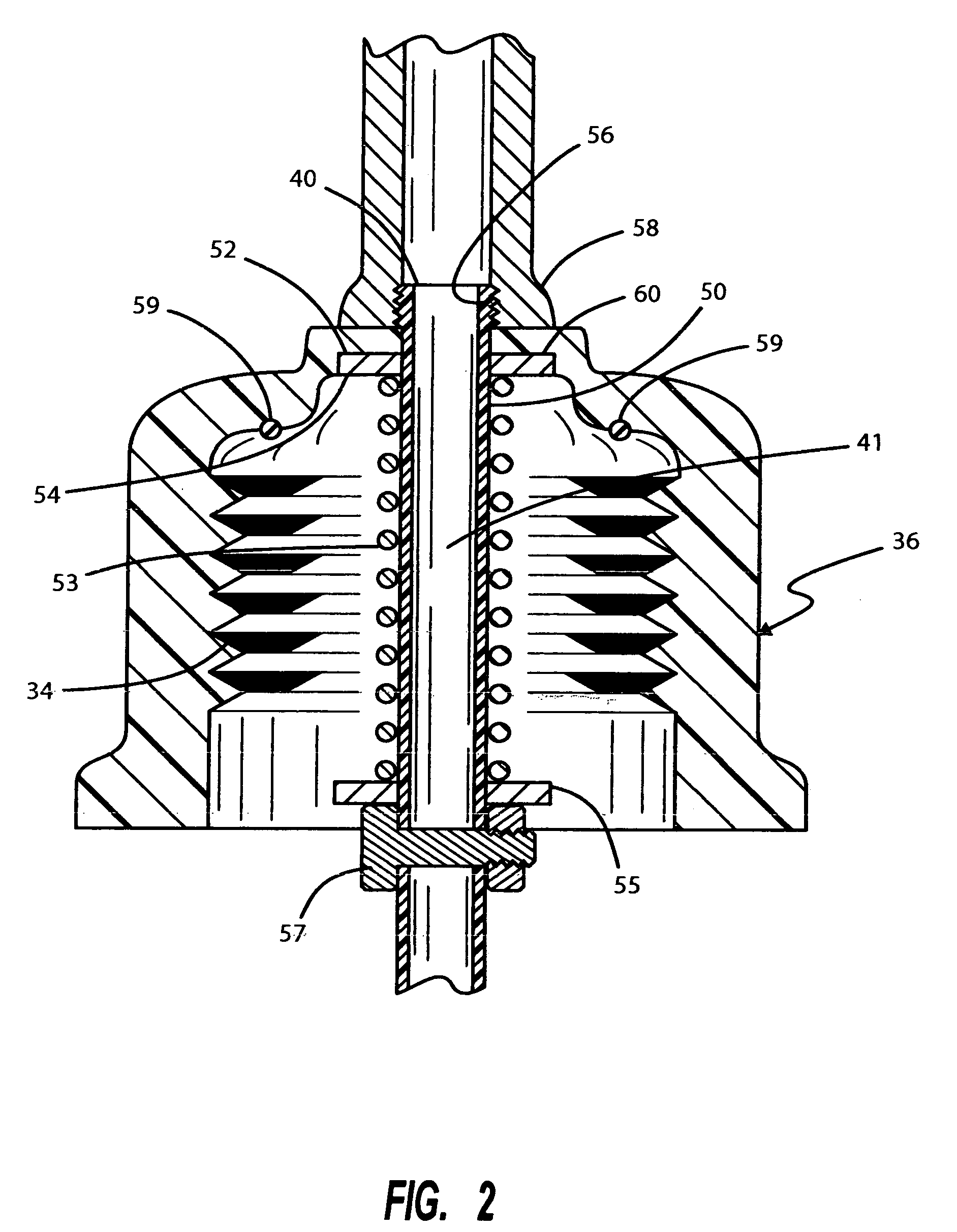
[0012]Referring to FIG. 1, there is illustrated by means of a perspective view a preferred embodiment of the fluid transfer apparatus of the present invention. It is indicated generally by numeral 10 and is seen to comprise a container 12, preferably formed from a suitable plastic, such as polyethylene, in a roto-molding operation so as to have a wall thickness of about 1 / 16th inch and a length, width and depth dimension giving the container a capacity of approximately five U.S. gallons. It is to be understood that these dimensions are exemplary and should not be considered as limiting of the invention. An adult can readily carry the container filled with five gallons of most liquids. The container has a bottom 14 and four mutually perpendicular side walls 16, 18, 20 and 22 rising upwardly from the bottom 14 for a predetermined distance then sloping upwardly and inwardly as at 22, 24, 26 and 28 to form a neck or spout 30. Formed integrally with the container or jug 12 is a carrying ...


PUM

PropertyMeasurementUnit
volumeaaaaaaaaaa
lengthaaaaaaaaaa
chargeaaaaaaaaaa

Abstract

A portable fluid transfer apparatus for handling volatile fuels or other chemicals comprises a jug-like container of a convenient volume having a removable cap that can be screwed or clamped onto the neck of the jug and mounted atop the cap is a manually operable rotary vane pump having a first inlet / outlet port disposed within the container when the cap is in place and a second inlet / outlet port external of the jug or container. An elongated, suction / discharge hose having a tether for anchoring the end of the hose in place is affixed to the second inlet / outlet. Manual actuation of the vane pump is then used to transfer a liquid from or into the portable container.

Description

BACKGROUND OF THE INVENTION[0001]I. Field of the Invention[0002]This invention relates generally to fluid transfer apparatus, and more particularly to a portable container for a liquid having a built-in, manual pump for transferring a liquid into or from the portable container.[0003]II. Discussion of the Prior Art[0004]There are many instances where a liquid must be dispensed from a first container to a second container rapidly and without any spillage. For example, in fueling an internal combustion engine, gasoline or diesel fuel must be carried in a portable container to the location of the engine fuel tank and the fuel poured from the transporting container into the fuel tank without spillage. This task becomes difficult where the entrance opening to the engine's fuel tank is relatively small in size or is at an angle to the horizontal or a difficult to reach location. In an attempt to address the small size issue, the prior art solution has generally been to utilize a funnel, bu...

Claims


Application Information

Patent Timeline
Patent Type & Authority Patents(United States)
IPC IPC(8): B65B1/08
CPCB67D7/0205
Inventor FRANKS, NORMAL ALTON
Owner FRANKS NORMAL ALTON
Why Eureka
Try Eureka