Cutting tool and cutting insert therefor

a cutting tool and cutting insert technology, applied in the field of cutting tools, can solve problems such as dislocation and particularly dangerous

Active Publication Date: 2007-01-16
ISCAR LTD
View PDF22 Cites 38 Cited by
  • Summary
  • Abstract
  • Description
  • Claims
  • Application Information

AI Technical Summary

Problems solved by technology

A well-known problem with cutting tools of the type described above is that the cutting insert is not positively secured in the insert pocket and therefore can become dislodged during cutting operations.
This problem can be especially troubling with rotary slot-cutting tools where the cutting insert can even fly out of the insert pocket under the influence of centrifugal forces, a situation that can be particularly dangerous when operating at high speeds.

Method used


Image

  • Cutting tool and cutting insert therefor
  • Cutting tool and cutting insert therefor
  • Cutting tool and cutting insert therefor

Examples


Embodiment Construction

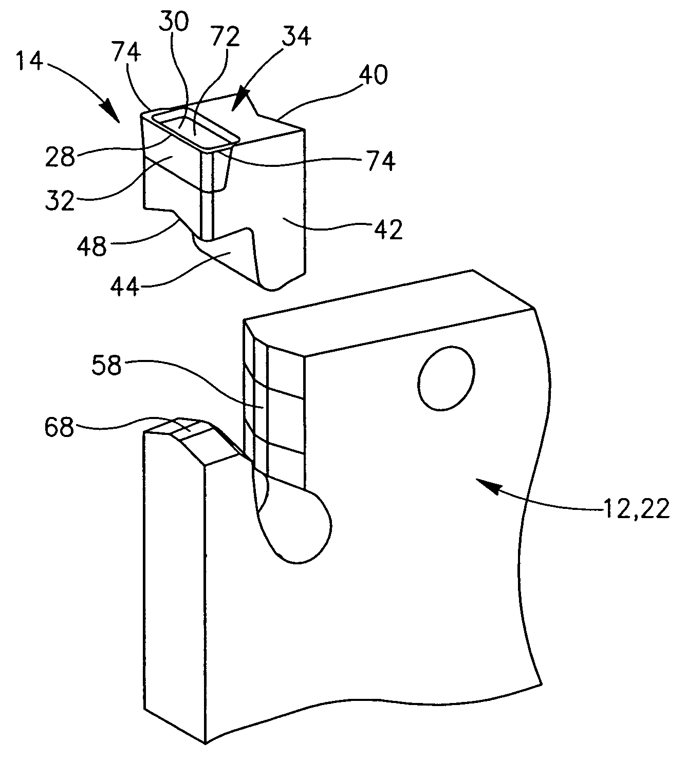
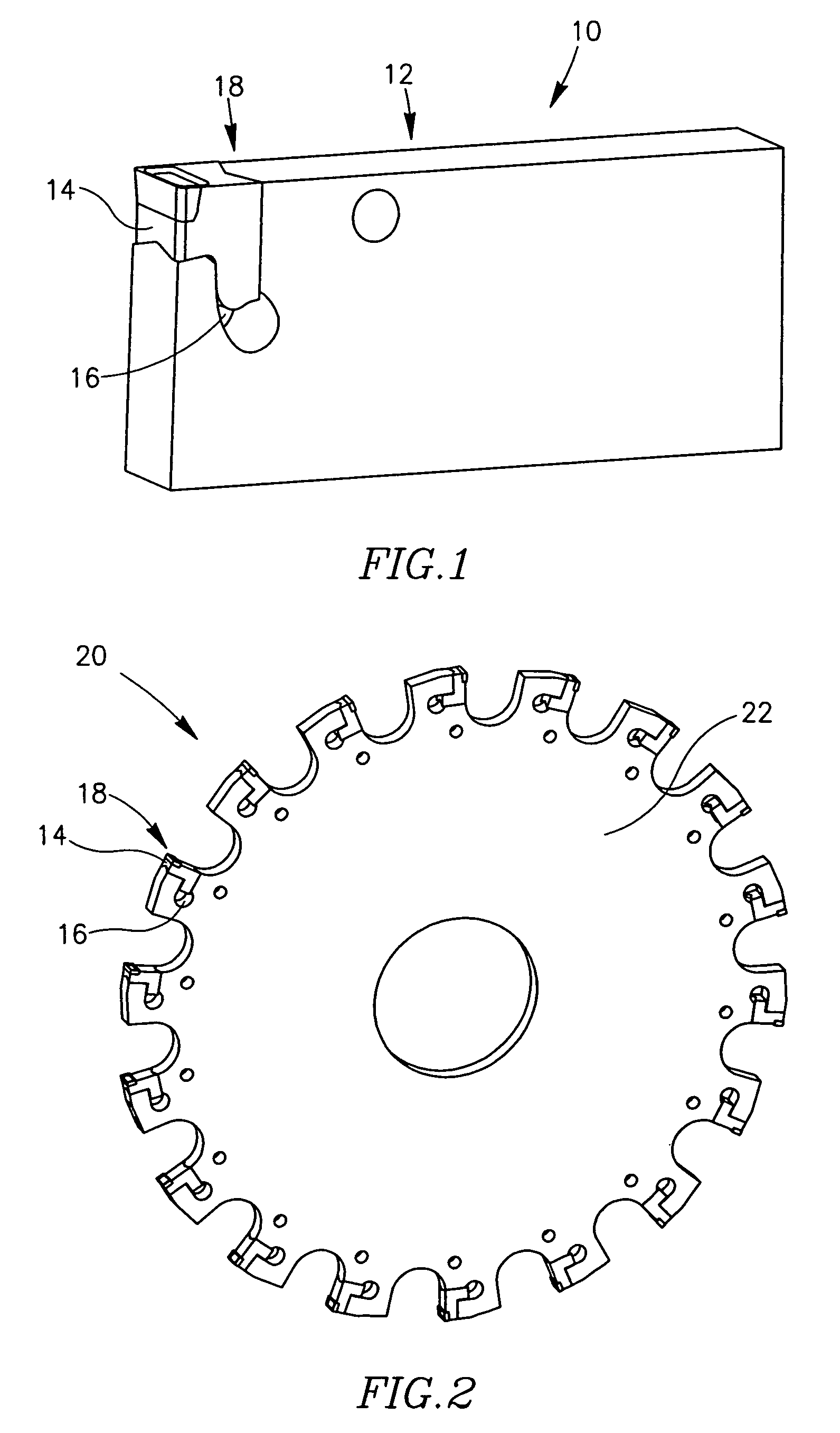
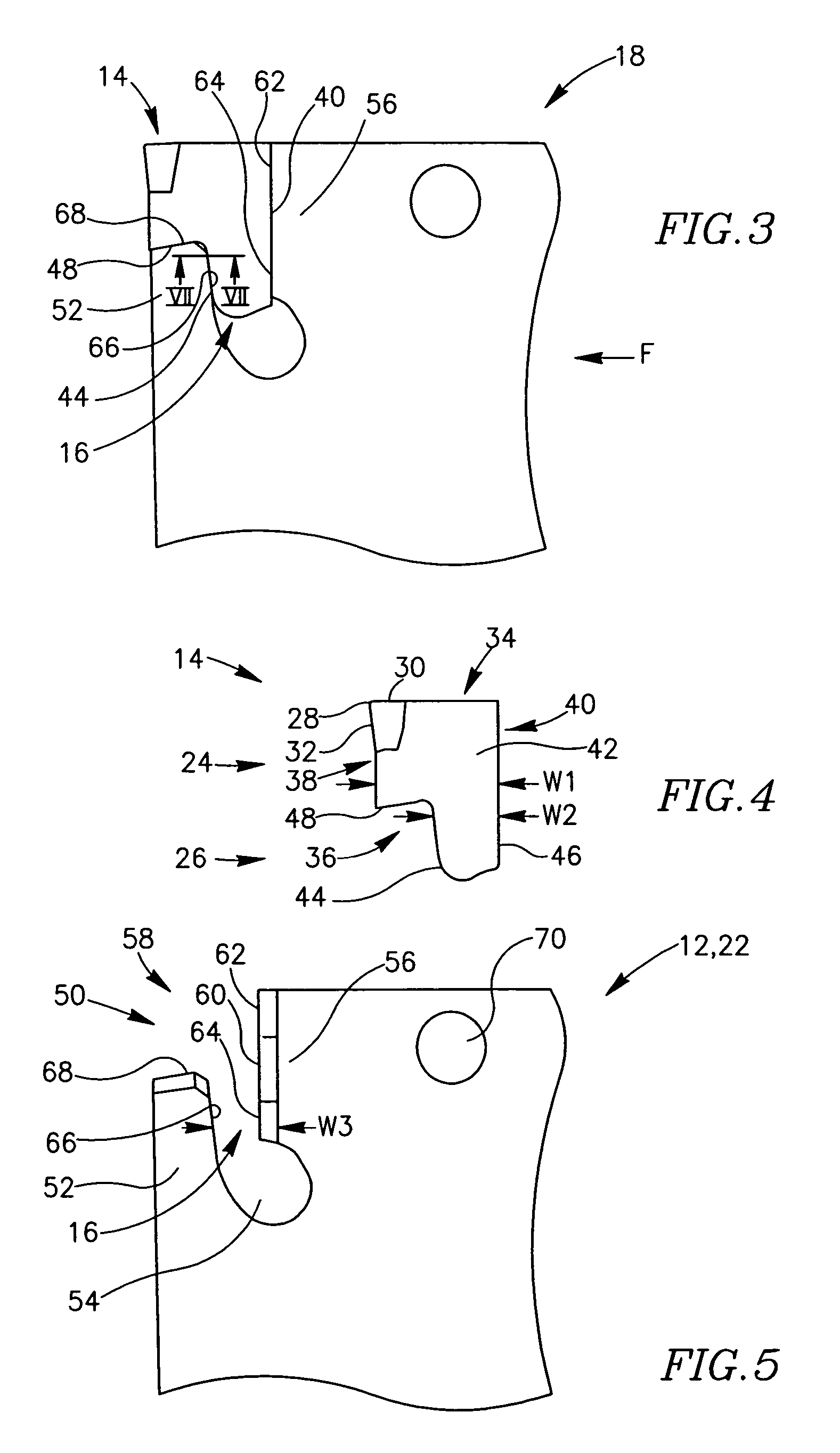
[0036]Attention is first drawn to FIGS. 1 and 2 showing two cutting tools in accordance with the present invention. FIG. 1 shows a first cutting tool 10 used for metal cutting operations such as grooving and parting off. The first cutting tool 10 comprises an insert holder12 in the form of a rectangular blade with a cutting insert 14 resiliently retained in an insert pocket 16. The cutting insert 14 is typically manufactured by form-pressing and sintering carbide powders. FIG. 2 shows a second cutting tool 20, used for rotary slot metal cutting operations. The second cutting tool 20 comprises an insert holder 22 in the form of a circular disc with cutting inserts 14 resiliently retained in identical insert pockets 16 arranged around the periphery of the disc. The cutting tools 10, 20 comprise a cutting section 18 which includes the cutting insert 14, the insert pocket 16 and the immediate vicinity of the insert pocket 16. The cutting section 18 is shown in FIG. 3. It should be noted...


PUM

PropertyMeasurementUnit
thicknessaaaaaaaaaa
degree of resilient displacementaaaaaaaaaa
thicknessaaaaaaaaaa

Abstract

A cutting tool in which a cutting insert is resiliently retained. The cutting insert includes a locating portion and a cutting portion having a rake surface and a relief surface. The locating portion extends from the cutting portion away from the rake surface.

Description

FIELD OF THE INVENTION[0001]The present invention relates to cutting tools of the type in which a cutting insert is resiliently clamped in a self-retaining manner in an insert pocket.BACKGROUND OF THE INVENTION[0002]Cutting tools employing a resilient clamping mechanism for clamping cutting inserts are generally of relatively narrow thickness, typically in the range of 0.5 mm to 12 mm and the cutting insert is retained in an insert pocket located between the clamping surfaces of upper and lower jaws of the cutting tool. In cutting operations such as grooving and parting off the cutting tool is in the form of a holder blade. The holder blade is, in turn, generally clamped in a blade-retaining block. The holder blade is generally provided with a suitably designed opening, in the vicinity of the insert pocket whereby a relatively narrow bridging portion is formed enabling a limited degree of resilient displacement of one of the holder blade's jaws relative to the other. Generally, the ...

Claims


Application Information

Patent Timeline
Patent Type & Authority Patents(United States)
IPC IPC(8): B23B29/04B23C5/08B23C5/22
CPCB23B29/043B23C5/08B23C5/22B23B2205/02B23C2210/161Y10T407/194Y10T407/2288Y10T407/23Y10T407/2286Y10T407/25B23C2210/486B23C5/2204
Inventor HECHT
Owner ISCAR LTD
Why Eureka
Try Eureka