Reformer exercise apparatus anchor bar assembly

Inactive Publication Date: 2007-01-16
BALANCED BODY INC
View PDF61 Cites 201 Cited by
  • Summary
  • Abstract
  • Description
  • Claims
  • Application Information

AI Technical Summary

Problems solved by technology

Another drawback with the conventional round bar and slotted bracket spring anchor design is that the brackets are separate components which must typically be installed at the foot end of the frame over the rails.

Method used


Image

  • Reformer exercise apparatus anchor bar assembly
  • Reformer exercise apparatus anchor bar assembly
  • Reformer exercise apparatus anchor bar assembly

Examples


Embodiment Construction

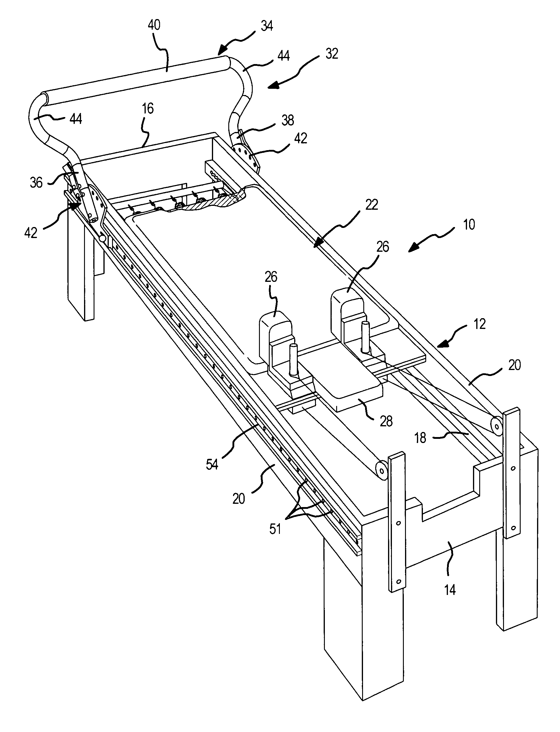
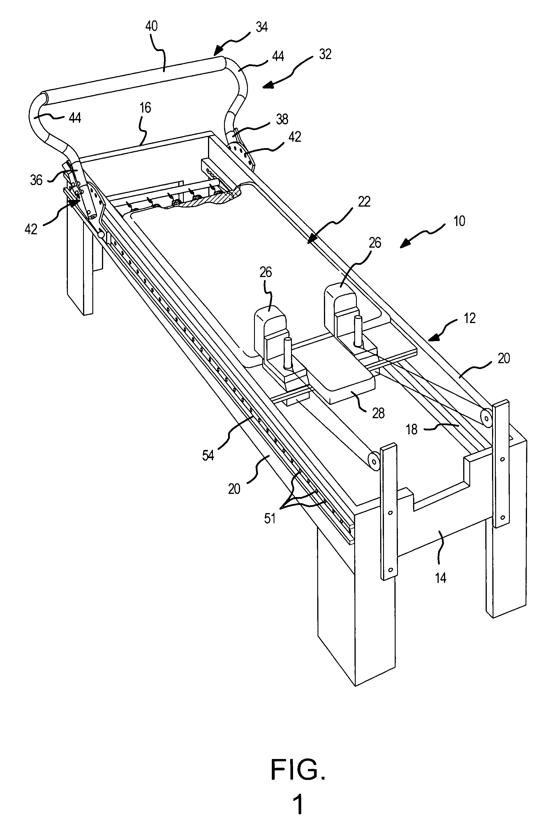
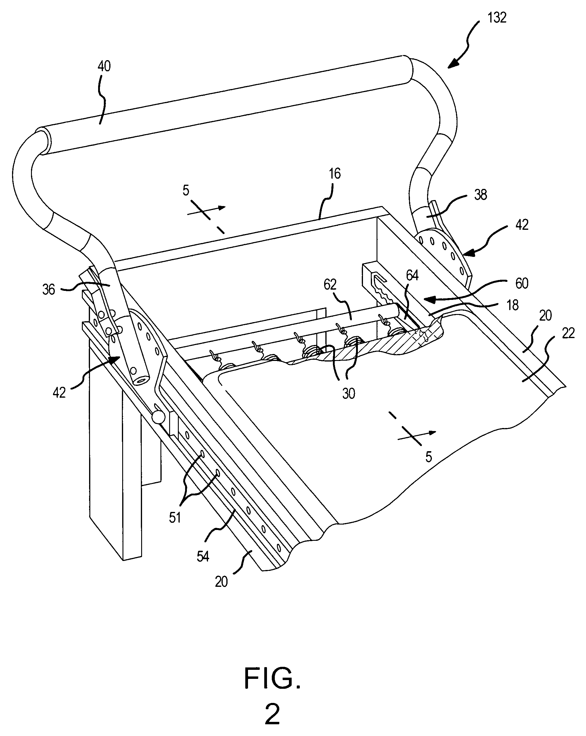
[0020]An exercise apparatus 10 in accordance with one embodiment of the present invention is shown in FIG. 1. Exercise apparatus 10 comprises a generally rectangular frame 12 having a head end 14 and a foot end 16 and a pair of parallel track members 18. The frame 12 may be a generally rectangular wood frame with the track members 18 fastened to the insides of opposite side walls 20 of the frame 12, or the track members 18 themselves may constitute the parallel side walls of the frame 12, as in a reformer having a metal tubular frame. The apparatus 10 further comprises a movable carriage 22 slidably or rollably disposed on the track members 18 for movement back and forth on the track members 18 between the head and foot ends 14 and 16 respectively.

[0021]Each of the track members 18 in the reformer apparatus 10 in accordance with the present invention is a metal tube that has a rectangular, and preferably a generally square cross-sectional shape. These metal tubes are, in the embodim...


PUM


Abstract

A reformer exercise apparatus has a generally rectangular frame having a head end and a foot end and including a pair of spaced apart parallel track members, a movable carriage mounted on the frame for movement along the track members between said head and foot ends against one or more springs connected between the carriage and the foot end of the frame and an elastic member anchor bar and carriage stop assembly to adjustably position the carriage and elastic members on the tracks to accommodate a wide range of user heights. The anchor bar and carriage stop assembly includes an anchor bar having each end disposed in an elongated slot formed in each track member. The elongated slot has spaced gear teeth defining spaced anchor bar stop or lock portions. The anchor bar can be moved between lock portions only when rotated to an unlocked position wherein the bar can operably slide along the slot.

Description

BACKGROUND OF THE INVENTION[0001]1. Field of the Invention[0002]This invention relates generally to the field of exercise equipment in which a movable carriage is utilized to at least partially support a user's body, commonly referred to as a “reformer”, and more particularly to a reformer having an adjustable spring anchor bar and carriage stop assembly.[0003]2. Description of the Related Art[0004]Joseph H. Pilates, in U.S. Pat. No. 1,621,477, originally developed the concept of using a wheeled platform carriage connected to a resistance device such as a set of weights in conjunction with a stationary frame to provide a variable resistance against which a user could push with his / her feet or pull with the arms while in a sitting or recumbent position in order to exercise the major muscle groups of the user's trunk, legs and / or arms. Since that time many changes and improvements in the design of such an apparatus were developed by Joseph Pilates, and more recently, have been evolved...

Claims


Application Information

Patent Timeline
Patent Type & Authority Patents(United States)
IPC IPC(8): A63B26/00A63B21/04A63B21/055A63B22/00A63B23/035
CPCA63B21/04A63B22/0007A63B22/0087A63B23/035A63B22/001A63B21/00065A63B21/023A63B21/0428A63B2225/09A63B2208/0252A63B2208/0257
Inventor ENDELMAN, KENJANOWSKI, BRIAN
Owner BALANCED BODY INC
Why Eureka
Try Eureka