Connector

a technology of connecting rods and connectors, applied in the direction of coupling device connection, securing/insulating coupling contact members, electrical apparatus, etc., can solve the problems of affecting the electrical connection between the female and male terminals, reducing the pressure of contact between the contact portions, and gradually worn contact parts, etc., to achieve smooth connection, easy fitting, and resistance to the insertion of the connection terminals.

Active Publication Date: 2007-01-30
YAZAKI CORP
View PDF26 Cites 11 Cited by
  • Summary
  • Abstract
  • Description
  • Claims
  • Application Information

AI Technical Summary

Benefits of technology

[0019](3) The connector of the above Paragraph (1) or Paragraph (2) is further characterized in that the front holder has a lance support portion, and when the front holder is retained with the front end portion of the terminal receiving chamber, the lance support portion abuts against the lance to prevent the elastic deformation of the lance.
[0028]In the connector of the present invention, the shaking of the connection terminal can be prevented without increasing a resistance to the insertion of the connection terminal, and the fitting connection of the connector to the mating connector, as well as the cancellation of this fitting connection, can be easily effected, and besides even when vibration is applied to the connector, the reliability of electrical connection of the connection terminal can be maintained.

Problems solved by technology

Therefore, for example, when vibration is applied to the connector, the female terminal 3 shakes or slightly moves back and forth within the terminal receiving chamber 2, and a relative slight sliding movement repeatedly occurs between contact portions of the female and male terminals 3 and 6, and therefore there is a fear that the contact portions are gradually worn, so that a pressure of contact between the contact portions decreases, thus adversely affecting the electrical connection between the female and male terminals.

Method used


Image

  • Connector
  • Connector
  • Connector

Examples


Embodiment Construction

” with reference to the accompanying drawings.

BRIEF DESCRIPTION OF THE DRAWINGS

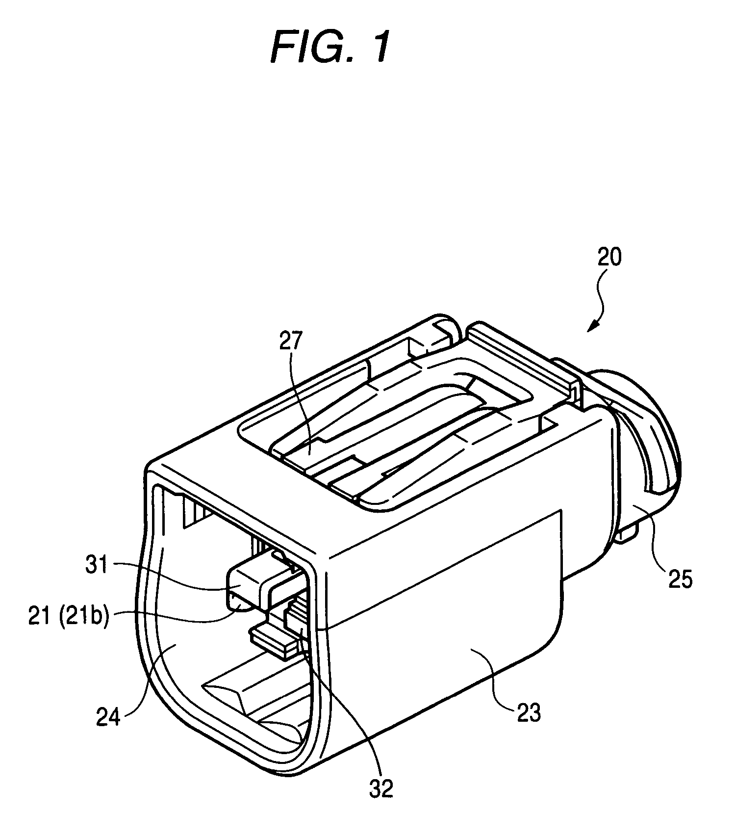
[0030]FIG. 1 is a perspective view of a connector housing of one preferred embodiment of a connector of the present invention.

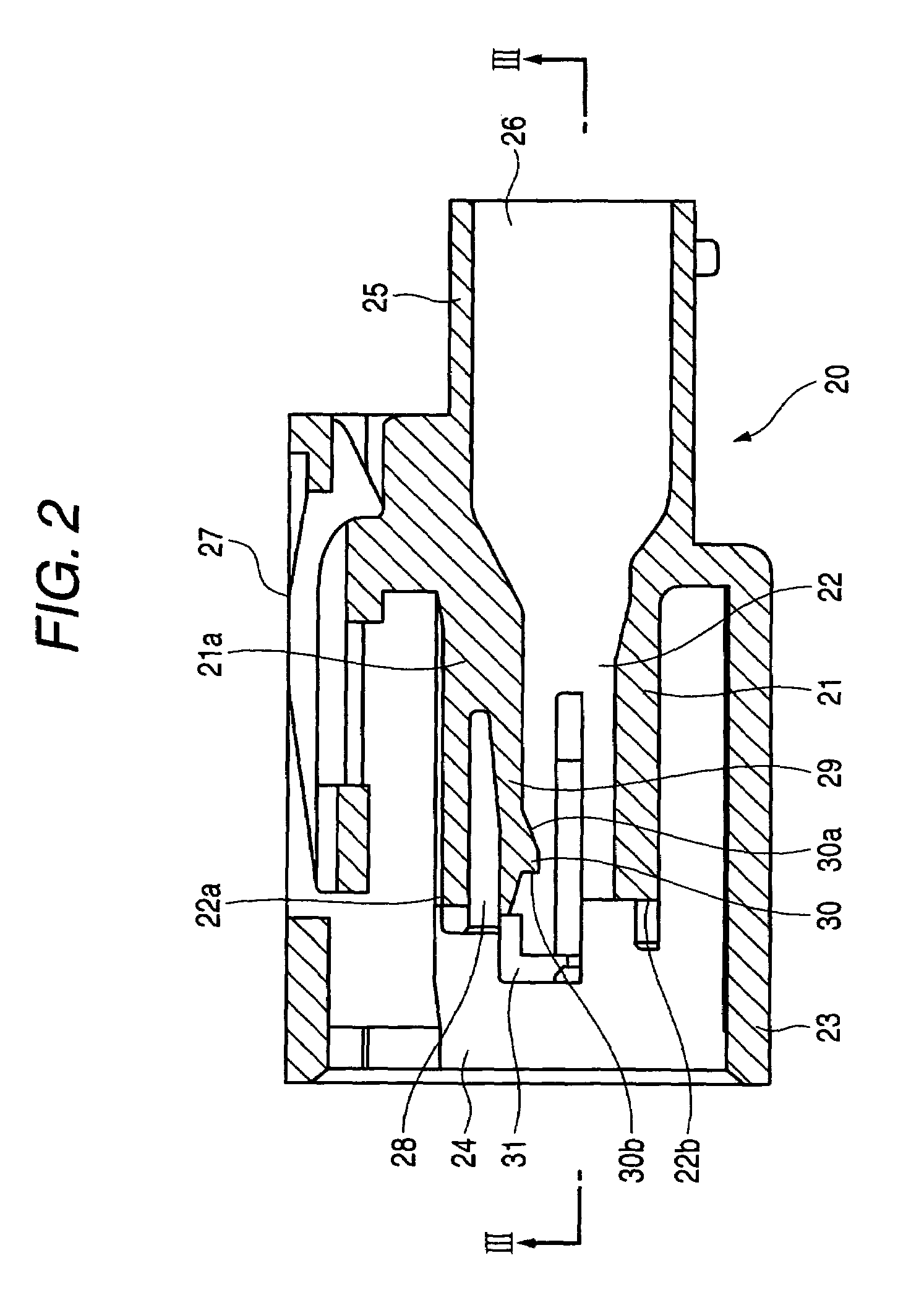
[0031]FIG. 2 is a vertical cross-sectional view of the connector housing of FIG. 1.

[0032]FIG. 3 is a cross-sectional view taken along the line III—III of FIG. 2.

[0033]FIG. 4 is a perspective view of a front holder of the connector of this embodiment.

[0034]FIG. 5 is a vertical cross-sectional view of the front holder of FIG. 4.

[0035]FIG. 6 is a cross-sectional view taken along the line VI—VI of FIG. 5.

[0036]FIG. 7 is a cross-sectional view taken along the line VII—VII of FIG. 5.

[0037]FIG. 8 is a partly broken side-elevational view of a connection terminal of the connector of this embodiment.

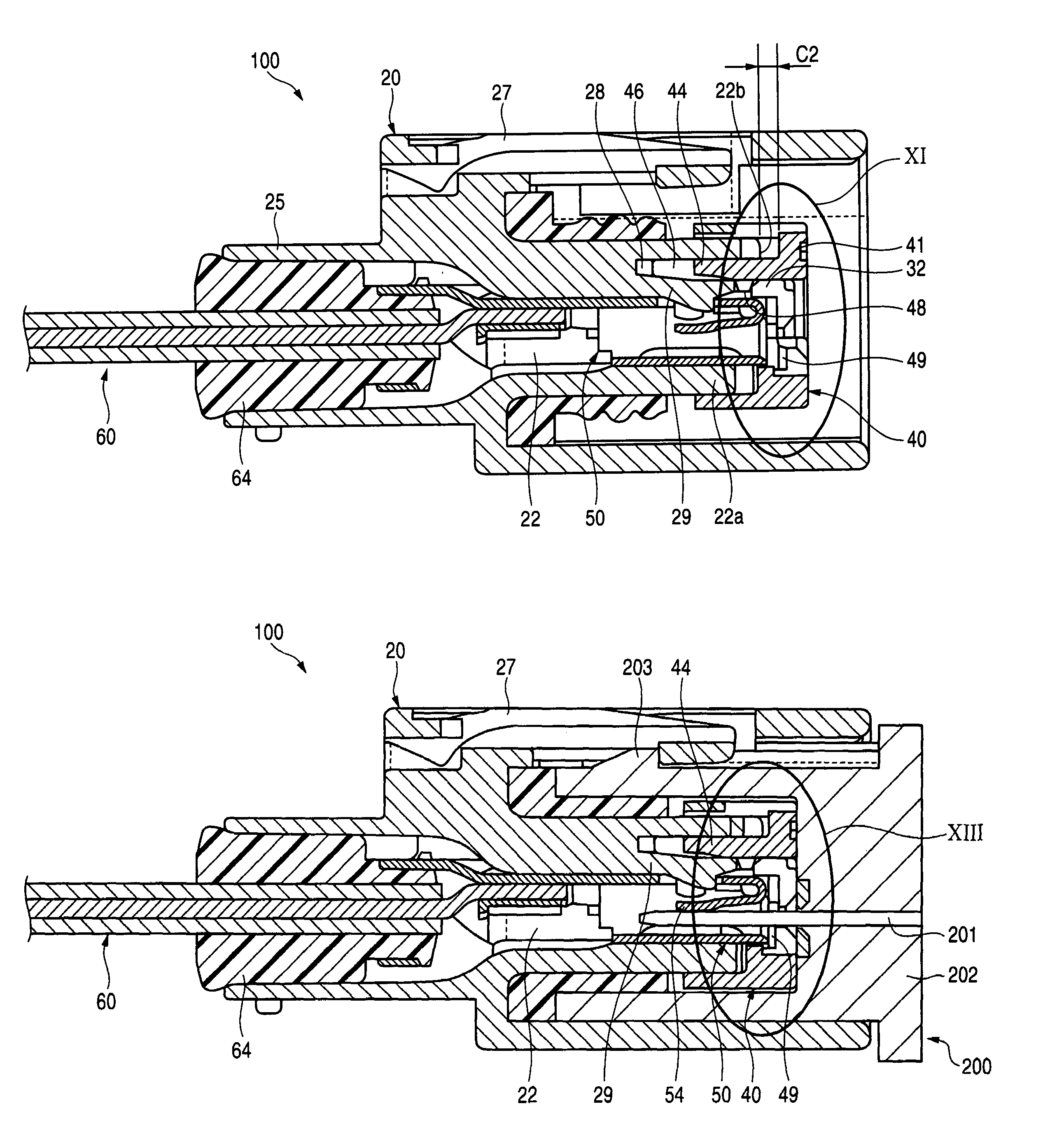
[0038]FIG. 9 is a vertical cross-sectional view of the connector, showing a condition in which the connection terminal is inserted in a terminal receiving chamber of the connector housing with wh...


PUM


Abstract

A connector comprising: a connection terminal; a connector housing having a terminal receiving chamber in which said connection terminal is inserted and a lance that is elastically deformable to engage the connection terminal in the connector housing; and a front holder supported on a front end portion of said terminal receiving chamber so as to be movable along said inserting direction; wherein said front holder is pressed by a mating connector to be moved in the opposite direction in accordance with a fitting movement of said connector relative to said mating connector; andwhen said connector is completely fitted relative to said mating connector, said front holder abuts against said connection terminal, and cooperates with said lance to hold said connection terminal therebetween.

Description

BACKGROUND OF THE INVENTION[0001]1. Field of the Invention[0002]This invention relates to a connector.[0003]2. Related Art[0004]In a connector of an ordinary structure as shown in FIG. 14, a female terminal 3 is inserted into a terminal receiving chamber 2, formed in a female connector housing 1, to be received therein, and is retained by a lance 4 against withdrawal. Similarly, a male terminal 6 is inserted into a terminal receiving chamber 2′, formed in a male connector housing 5, to be received therein, and is retained by a lance 4′ against withdrawal. When the female and male connector housings 1 and 5 are fitted together, the corresponding female and male terminals 3 and 6 are connected together (see, for example, JP-U-03-055674).[0005]Detailed description will be made of the structure of holding the terminal in the terminal receiving chamber against withdrawal. With respect, for example, to the female connector housing 1 shown in FIG. 14, the lance 4 has a projection 7 formed ...

Claims


Application Information

Patent Timeline
Patent Type & Authority Patents(United States)
IPC IPC(8): H01R13/40
CPCH01R13/4223H01R13/4365H01R13/424
Inventor TAKAHASHI, TOSHIHARU
Owner YAZAKI CORP
Why Eureka
Try Eureka