

Magnetic head including a gap-depth defining layer on protruding layer and method for manufacturing the same
a technology of gap-depth defining layer and magnetic head, which is applied in the field of recording thin-film magnetic head, can solve the problems of imposing more severe requirements on thin-film magnetic head, unable to reliably form thin upper magnetic pole layer b>11/b>, and magnetic head cannot be properly compatible with higher recording densities, etc., to achieve shorten the magnetic path and improve the recording characteristics
- Summary
- Abstract
- Description
- Claims
- Application Information
AI Technical Summary
Benefits of technology
Problems solved by technology
Method used
Image

Examples
first embodiment
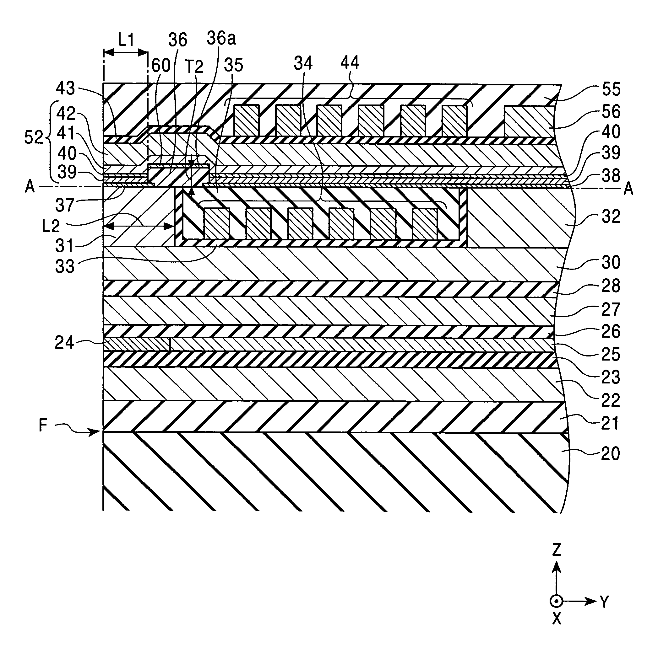
[0095]FIG. 1 is a longitudinal sectional view of a thin-film magnetic head according to the present invention.
[0096]In the drawings, X indicates a track-width direction; Y indicates a height direction of magnetic heads orthogonal to the track-width direction; and Z indicates a traveling direction of the magnetic heads over a recording medium (magnetic disc). In FIG. 1, F indicates the front surface (the leftmost surface in the drawing) of the magnetic head. This front surface faces the recording medium.
[0097]An Al2O3 layer 21 is formed on a substrate 20 of, for example, alumina-titanium carbide (Al2O3—TiC).
[0098]A lower shield layer 22 of, for example, Ni—Fe alloy or sendust is formed on this Al2O3 layer 21, and a lower gap layer 23 of, for example, Al2O3 is formed on this lower shield layer 22.
[0099]A magnetoresistive device 24, typically a giant magnetoresistive (GMR) device such as a spin-valve thin-film device, is formed on this lower gap layer 23 near the front surface of the m...
second embodiment
[0228]FIG. 25 is a partial longitudinal sectional view of a magnetic head according to the present invention.
[0229]This magnetic head in FIG. 25 has a similar structure to that in FIG. 1. Therefore, the same parts as the magnetic head in FIGS. 1 to 4 will be indicated by the same numbers and not described in detail.
[0230]The magnetic head in FIG. 25 is different from that in FIG. 1 in that the rear end surface 36c of the gap-depth defining layer 36 is positioned on the back gap layer 32.
[0231]Alternatively, the rear end surface 36c of the gap-depth defining layer 36 may be positioned on the boundary between the top surface and front end surface of the back gap layer 32.
[0232]In this magnetic head, the gap-depth defining layer 36 overlaps entirely with the first coil segments 34 to strengthen the insulation between the first coil segments 34 and the upper magnetic pole layer 41.
[0233]The upper magnetic pole layer 41 can be insulated even if the first coil segments 34 extend to the re...
third embodiment
[0238]FIG. 27 is a partial longitudinal sectional view of a magnetic head according to the present invention. This magnetic head in FIG. 27 has a similar structure to that in FIG. 1. Therefore, the same parts as the magnetic head in FIGS. 1 to 4 will be indicated by the same numbers and not described in detail.
[0239]The magnetic head in FIG. 27 has a different coil layer 82 from that in FIG. 1.
[0240]This magnetic head includes a leveling layer 80 that has a top surface at the same level as that of the lower core layer 30 and that is disposed behind the lower core layer 30. The leveling layer 80 is separated from the rear end surface 30a of the lower core layer 30 by a predetermined distance. The space between the lower core layer 30 and the leveling layer 80 is filled with a nonmagnetic layer 81 made of, for example, Al2O3. The lower core layer 30, the leveling layer 80, and the nonmagnetic layer 81 form a continuous, flat top surface.
[0241]The coil-insulating seed layer 33 is forme...
PUM
| Property | Measurement | Unit |
|---|---|---|
| total thickness | aaaaa | aaaaa |
| saturation magnetic flux densities | aaaaa | aaaaa |
| saturation magnetic flux densities | aaaaa | aaaaa |
Abstract
Description
Claims
Application Information