Magnetic head for perpendicular magnetic recording including a coil element located between the top surface of a main pole and an inclined surface of a shield

a perpendicular magnetic recording and magnetic head technology, applied in the direction of magnetic recording heads, data recording, instruments, etc., can solve the problems of insufficient reduction of the length of the magnetic path that passes through the write shield, degradation of the write characteristics such as the overwrite property, and the degradation of the overwrite property, so as to achieve the effect of shortening the magnetic path and improving the write characteristics

Active Publication Date: 2013-02-26
HEADWAY TECH INC +2
View PDF13 Cites 15 Cited by
  • Summary
  • Abstract
  • Description
  • Claims
  • Application Information

AI Technical Summary

Benefits of technology

[0018]It is an object of the present invention to provide a magnetic head for perpendicular magnetic recording that makes it possible to avoid the problems induced by

Problems solved by technology

This makes it difficult for the main pole to direct much magnetic flux to the medium facing surface, thus leading to degradation of overwrite property.
The above-described configuration, however, has a problem in that where the inclined portion of the top surface of the main pole and the inclined surface of the write shield are opposed to each other over a large area with a small spacing therebetween, magnetic flux leakage from the main pole to the write shield

Method used


Image

  • Magnetic head for perpendicular magnetic recording including a coil element located between the top surface of a main pole and an inclined surface of a shield
  • Magnetic head for perpendicular magnetic recording including a coil element located between the top surface of a main pole and an inclined surface of a shield
  • Magnetic head for perpendicular magnetic recording including a coil element located between the top surface of a main pole and an inclined surface of a shield

Examples


first embodiment

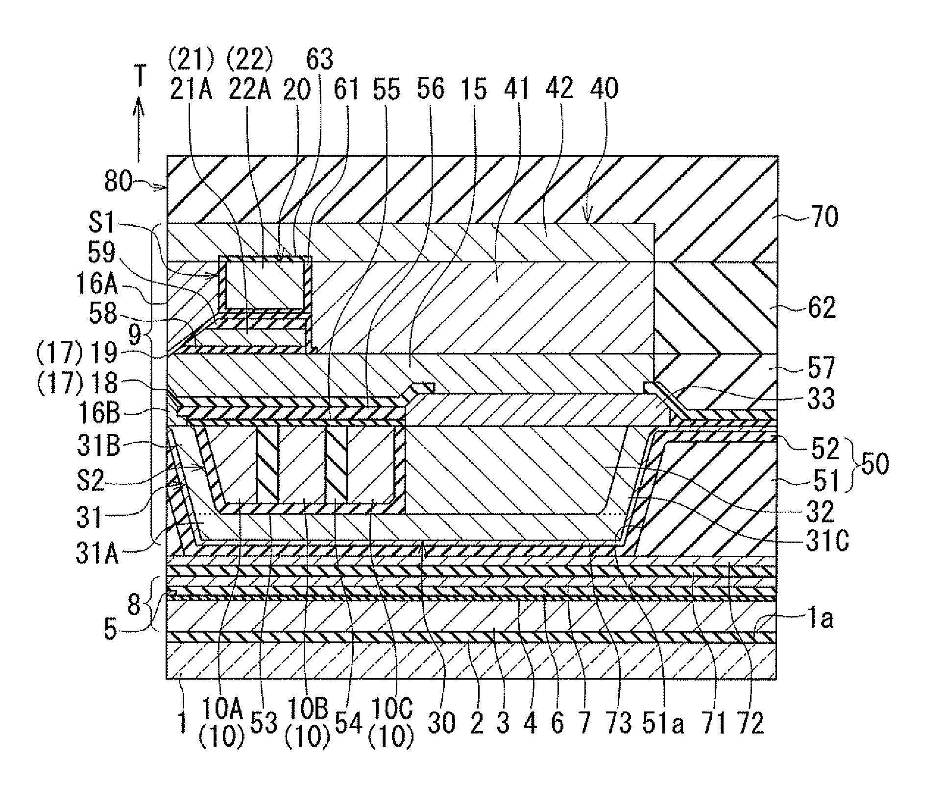
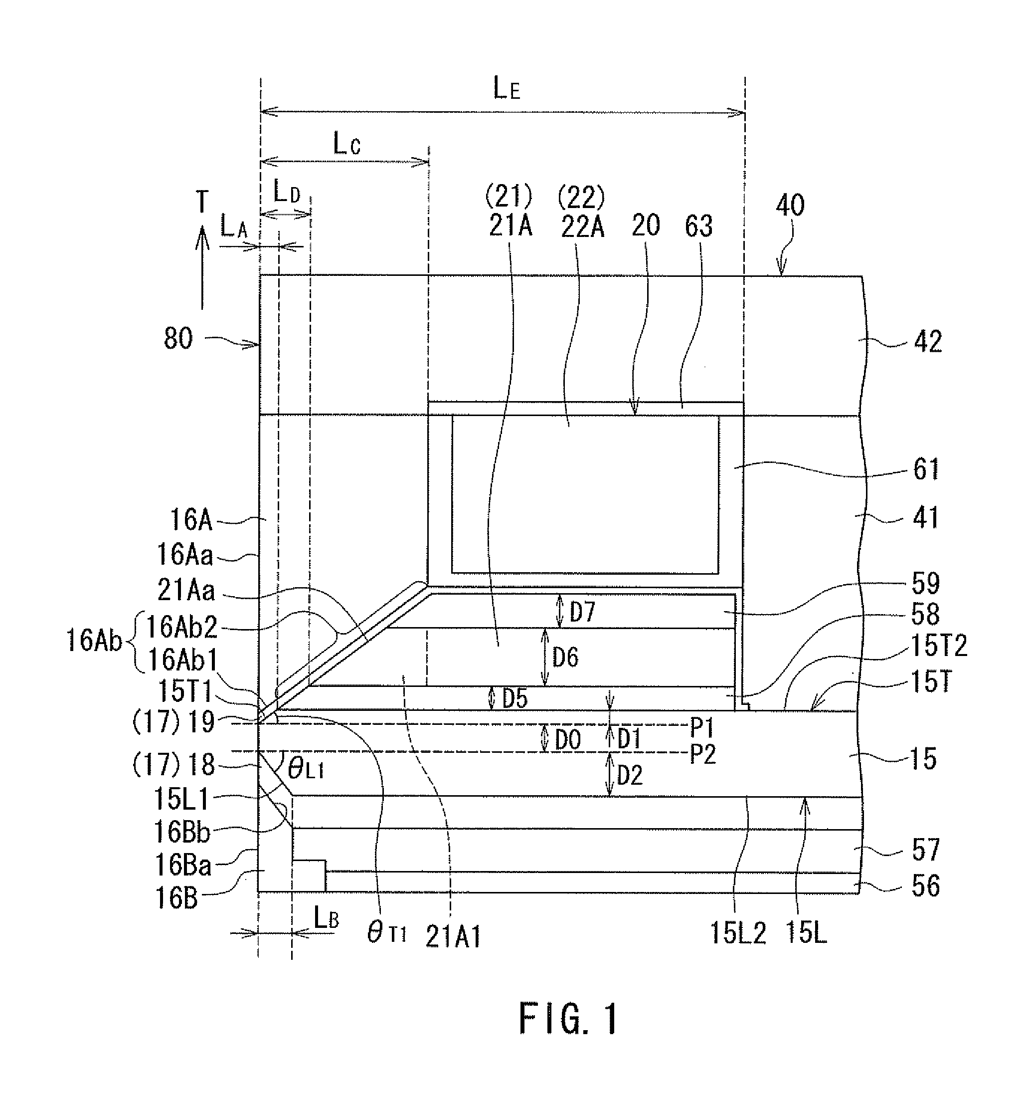
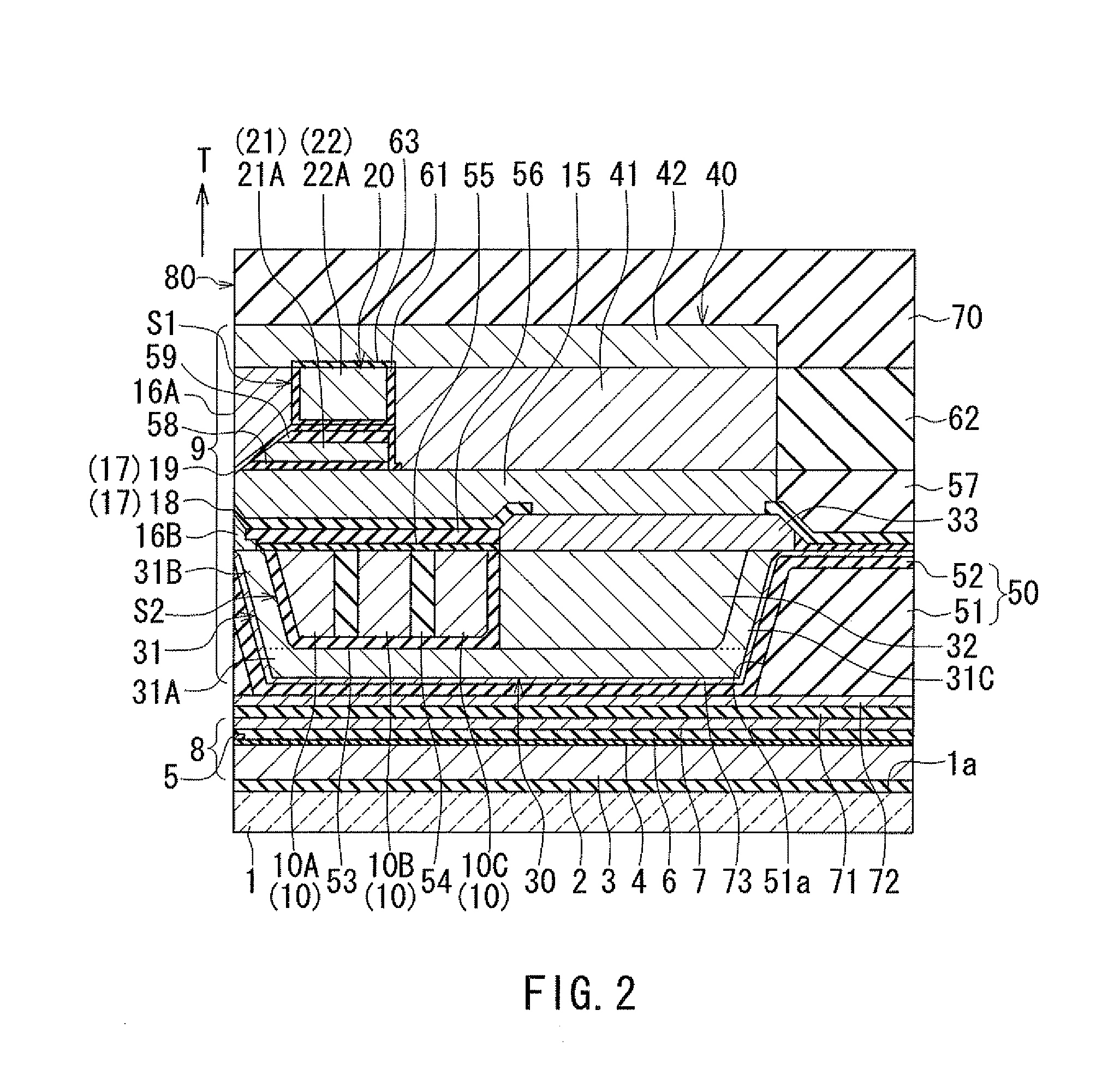
[0047]Embodiments of the present invention will now be described in detail with reference to the drawings. First, reference is made to FIG. 1 to FIG. 6 to describe the configuration of a magnetic head according to a first embodiment of the invention. FIG. 1 is a cross-sectional view showing the main part of the magnetic head according to the present embodiment. FIG. 2 is a cross-sectional view of the magnetic head according to the present embodiment. Note that FIG. 1 and FIG. 2 show cross sections perpendicular to the medium facing surface and to the top surface of the substrate. The arrows with the symbol T in FIG. 1 and FIG. 2 indicate the direction of travel of the recording medium. FIG. 3 is a front view showing the medium facing surface of the magnetic head according to the present embodiment. FIG. 4 is a plan view showing a second portion of a coil of the magnetic head according to the present embodiment. FIG. 5 is a plan view showing a first layer of a first portion of the co...

second embodiment

[0132]A magnetic head according to a second embodiment of the invention will now be described with reference to FIG. 11. FIG. 11 is a cross-sectional view showing the main part of the magnetic head according to the present embodiment. FIG. 11 shows a cross section perpendicular to the medium facing surface and to the top surface of the substrate, or the main cross section, in particular.

[0133]The configuration of the magnetic head according to the present embodiment is different from that of the magnetic head according to the first embodiment in the following respects. The top surface 15T of the main pole 15 of the present embodiment includes a first inclined portion 15T1, a first flat portion 15T2, a second inclined portion 15T3, and a second flat portion 15T4 contiguously arranged in this order, the first inclined portion 15T1 being closest to the medium facing surface 80. The first inclined portion 15T1 has a first end located in the medium facing surface 80 and a second end oppo...

third embodiment

[0147]A magnetic head according to a third embodiment of the invention will now be described with reference to FIG. 12. FIG. 12 is a cross-sectional view showing the main part of the magnetic head according to the present embodiment. FIG. 12 shows a cross section perpendicular to the medium facing surface and to the top surface of the substrate, or the main cross section, in particular.

[0148]The configuration of the magnetic head according to the present embodiment is different from that of the magnetic head according to the first embodiment in the following respects. The first portion 20 of the coil of the present embodiment includes a first layer 121 in place of the first layer 21 of the first embodiment. The first layer 121 is wound one turn around the columnar portion 41 which constitutes part of the first return path section 40.

[0149]In the present embodiment, the insulating layer 19 is not formed above the top surface of the first layer 121. The insulating layer 59 covers the ...


PUM


Abstract

A magnetic head includes a coil, a main pole, a write shield, a gap part, and a return path section. The return path section is located on the front side in the direction of travel of a recording medium relative to the main pole, and connects the write shield and part of the main pole away from a medium facing surface to each other. The coil includes a specific coil element. The main pole has a top surface including an inclined portion and a flat portion. The write shield has an inclined surface. The inclined surface includes a first portion opposed to the inclined portion with the gap part therebetween, and a second portion located farther from the medium facing surface than the first portion. The specific coil element includes a portion interposed between the flat portion and the second portion.

Description

BACKGROUND OF THE INVENTION[0001]1. Field of the Invention[0002]The present invention relates to a magnetic head for perpendicular magnetic recording that is used for writing data on a recording medium by means of a perpendicular magnetic recording system, and more specifically, to a magnetic head for perpendicular magnetic recording that has a main pole and a shield.[0003]2. Description of Related Art[0004]The recording systems of magnetic read / write apparatuses include a longitudinal magnetic recording system wherein signals are magnetized in a direction along the plane of the recording medium (the longitudinal direction) and a perpendicular magnetic recording system wherein signals are magnetized in a direction perpendicular to the plane of the recording medium. It is known that the perpendicular magnetic recording system is harder to be affected by thermal fluctuation of the recording medium and capable of providing higher linear recording density, compared with the longitudinal...

Claims


Application Information

Patent Timeline
IPC IPC(8): G11B5/127
CPCG11B5/1278G11B5/3116G11B5/3123
Inventor SASAKI, YOSHITAKAITO, HIROYUKISATO, KAZUKITANEMURA, SHIGEKIARAKI, HIRONORISHIMIZU, TATSUYA
Owner HEADWAY TECH INC
Why Eureka
Try Eureka