Dual-layer recordable optical recording medium

a recording medium and recordable technology, applied in mechanical recording, record information storage, instruments, etc., can solve the problems of low carrier-to-noise ratio, increase manufacturing costs, and reduce the commercial value of the disc, so as to improve the recording characteristics of the first information layer, high reflectivity, and high sensitivity

Inactive Publication Date: 2007-10-11
RICOH KK
View PDF0 Cites 16 Cited by
  • Summary
  • Abstract
  • Description
  • Claims
  • Application Information

AI Technical Summary

Benefits of technology

[0025] According to the present invention, in a dual-layer recordable optical recording medium in which a Re layer is used as a recording layer, it is possible to improve recording characteristics of the first information layer by use of the thermal diffusion layer of the present invention. Thus, it is possible to provide a dual-layer recordable optical recording medium which offers high reflectivity and high sensitivity and which has a simple layer configuration capable of realizing a large refraction index and small absorption coefficient over the recording / reproduction beam wavelength range for high-density recording.

Problems solved by technology

Manufacture of a recordable optical recording medium provided with inorganic recording layer(s) entails an increase in manufacturing costs if the number of layers to be deposited is large, and hence the commercial value of the disc is reduced.
The ablative recording holds promise in light of cost, but has a problem of low C / N ratio (Carrier to Noise ratio), which is caused due to the presence of a polka-dot film melted in the pits on the disc and / or the presence of a melted film on the peripheries of the pits.
In addition, as the ablative recording media adopts a single layer structure, general recording films cannot support high reflectance of ROM discs, resulting in products that do not meet standards.
Materials suitable for ablative recording include Te—Au compounds and Te—Ag compounds (see for instance Japanese Patent Application Laid-Open (JP-A) Nos. 60-179952 and 60-179953), but these materials have boiling points of 1,000° C. or higher, resulting in optical recording media with poor sensitivity.
For this reason, the ablative recording disc requires higher laser power than the phase change disc, and upon high-linear velocity recording on the ablative recording disc, it results in semiconductor laser power shortage.
Accordingly, compatibility with ROM discs cannot be established.
In addition, although the invention uses Au, Ag, and the like as corrosion-resistant metals, they have extremely high thermal conductivity and thus energy generated by heating is dissipated by diffusion, resulting in low effects of enhancing recording sensitivity and the resultant optical media are not suitable for high-linear velocity recording.
This method, however, results in low-to-high recording, and compatibility with ROM discs cannot be established.
For this reason, the number of necessary steps for initialization increases, so too does the manufacturing costs.
This recording medium, however, is disadvantageous in terms of take time and manufacturing costs because the first and second layers are made thick for high reflectance—300-700 Å for the first layer and 500-1,500 Å for the second layer.
An investigation conducted by the present inventors indicated that this high reflectance achieved by thickening the first and second layers resulted in poor recording sensitivity, because thermal absorption hardly occurred on the recording films due to their high reflectance that led to low thermal absorption.
Thus, this recording medium cannot be used as a medium that requires high-linear velocity, such as DVD.
However, this recording medium was found to be significantly unstable due to the high reactivity between In and Te or the like, as was the recording medium disclosed in JP-B No. 2948899.
The foregoing problems have significantly prevented widespread use of recordable optical recording media that include recording layer(s) made of inorganic material plus a small number of other layers.
To be more specific, Bi is an element that requires a mechanism for rapid cooling of the medium, and discs with thin reflective layers, like single-side, dual-layer discs, have a problem that formation of small marks becomes difficult.
Nitrides and carbides, however, are more likely to generate cracks on the thermal diffusion layer due to their high stress, resulting in insufficient overwrite characteristics in the optical disc provided with a thermal diffusion layer.
Moreover, carbides absorb light to a great extent particular at shorter wavelengths, leading to a problem that the transmittance of the first information layer made of carbide cannot be made large in such a next-generation system as the Blu-ray Disc system employing violet-blue laser.

Method used


Image

  • Dual-layer recordable optical recording medium
  • Dual-layer recordable optical recording medium
  • Dual-layer recordable optical recording medium

Examples


example 1

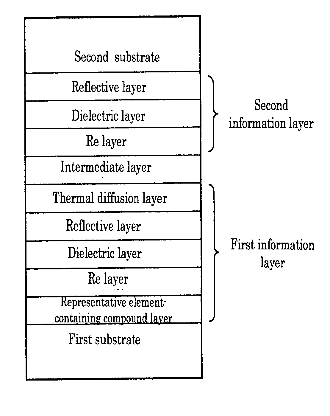
[0100] First and second substrates made of polycarbonate resin were first prepared, each of which is 120 mm in diameter and 0.58 mm in thickness and has a groove (depth=21 nm; track pitch=0.43 μm) on its surface

[0101] In single-wafer sputtering equipment (Balzers), a representative element-containing compound layer which is made of Al2O5 and 20 nm in thickness, a Re layer which is made of Bi2O3 and 20 nm in thickness, a dielectric layer which is made of ZnS—SiO2 (80:20(mol %)) and 20 nm in thickness, a reflective layer which is made of Ag and 156 nm in thickness, and a thermal diffusion layer which is made of IZO and 50 nm in thickness, were sequentially deposited on the first substrate to form a first information layer.

[0102] In a similar way, a reflective layer which is made of Ag and 100 nm in thickness, a dielectric layer which is made of ZnS—SiO2 (80:20(mol %)) and 20 nm in thickness, and a Re layer which is made of Bi2O3 and 20 nm in thickness, were sequentially deposited on...

example 2

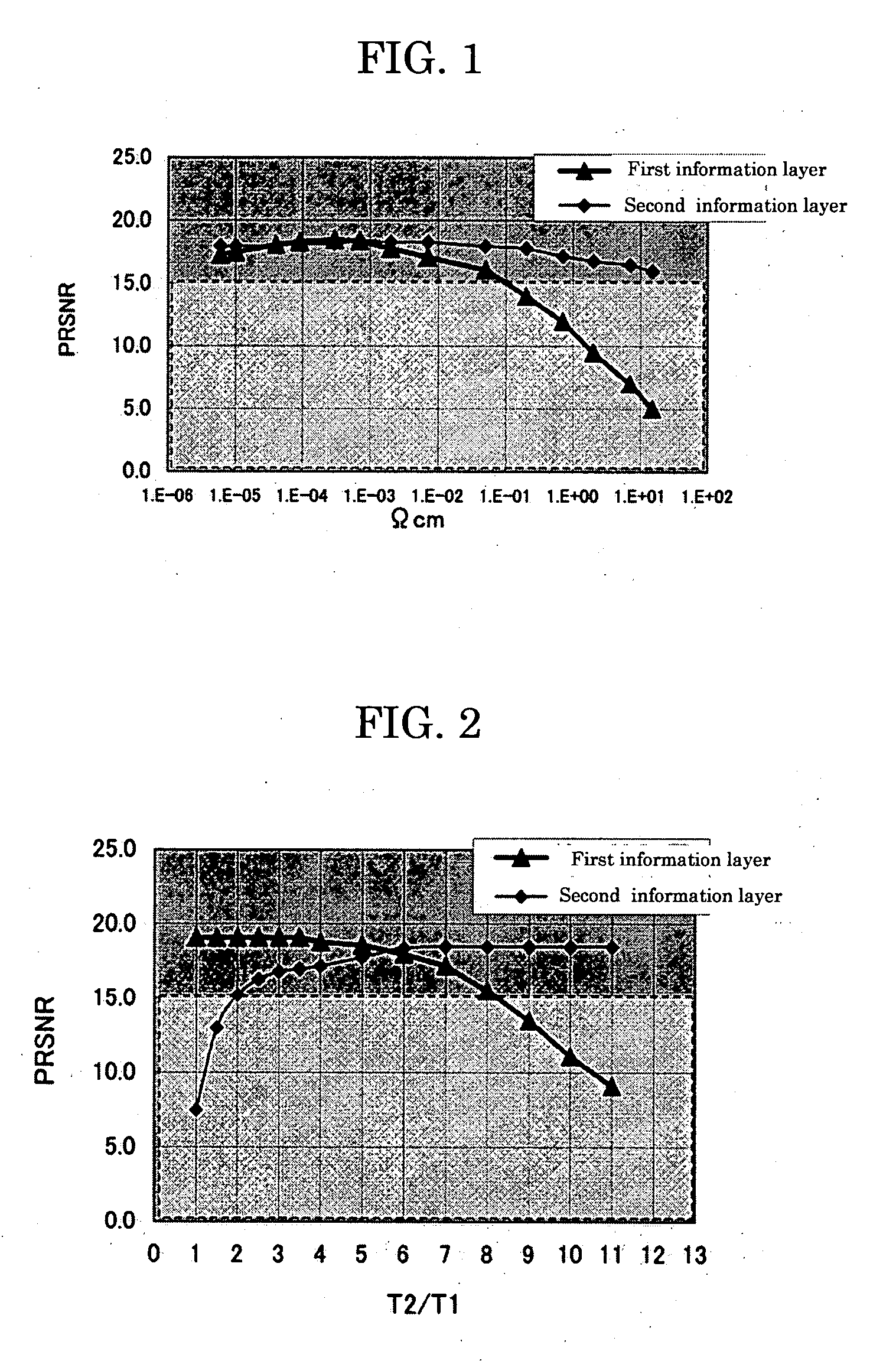
[0108] Dual-layer recordable optical recording media were manufactured in a manner similar to that described in Example 1 except that various T2 / T1 ratios were set by changing T1 (the thickness of the Ag reflective layer of the first information layer) and T2 (the thickness of the IZO thermal diffusion layer), and PRNSR values were measured. More specifically, various T2 / T1 ratios were obtained by setting the Ag reflective layer thickness (T1) to 10 nm, 15 nm and 20 nm and by setting various thicknesses (T2) for each thickness.

[0109] As can be seen from the measurement results shown in FIG. 2, the line corresponding to PRSNR of the second information layer showed a rapid decline at T2 / T12 / T1>8.

example 3

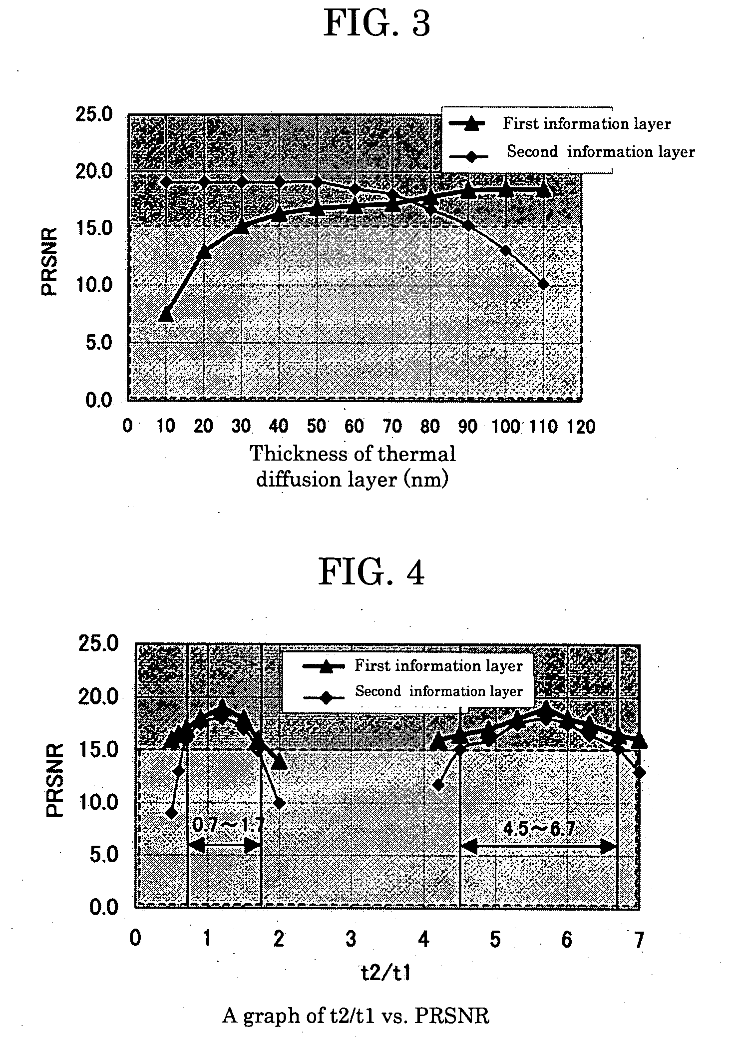
[0110] Dual-layer recordable optical recording media were manufactured in a manner similar to that described in Example 1 except that thermal diffusion layers with various thicknesses were used. PRSNR values were then measured.

[0111] As can be seen from the measurement results shown in FIG. 3, the line corresponding to PRSNR of the first information layer showed a rapid decline at the thermal diffusion layer thickness90 nm.


PUM

PropertyMeasurementUnit
thicknessaaaaaaaaaa
thicknessaaaaaaaaaa
thicknessaaaaaaaaaa

Abstract

To provide a dual-layer recordable optical recording medium, including: a first information layer; intermediate layer disposed over the first information layer; and second information layer disposed over the intermediate layer, the first information layer, intermediate layer, and second information layer being sequentially deposited from a laser irradiation side, wherein the first information layer comprises, from the laser irradiation side, at least a thin film containing Bi as a main ingredient, dielectric layer, reflective layer and thermal diffusion layer, and the second information layer comprises, from the laser irradiation side, at least a thin film containing Bi as a main ingredient, dielectric layer and reflective layer, and wherein the ratio of the thickness of the dielectric layer of the second information layer (t2) to the thickness of the dielectric layer of the first information layer (t1), t2/t1, is in a range of 0.7 to 1.5 or 4.5 to 6.0.

Description

BACKGROUND OF THE INVENTION [0001] 1. Field of the Invention [0002] The present invention relates to a recordable (Write Once Read Many (WORM)) optical recording medium capable of high-density recording thereon even over a blue laser wavelength range and, more specifically, to a dual-layer recordable optical recording medium having at least a first information layer, an intermediate layer, and a second information layer. [0003] 2. Description of the Related Art [0004] Examples of optical recording media capable of recording by irradiation with a laser beam are, for example, recordable optical recording media such as CD-R and DVD-R. These optical recording media are supported for compatibility with CD-ROM and DVD-ROM in terms of information reproduction and are used both as small scale-distribution media and storage media. At present, however, organic dye-based CD-R and DVD-R are used in most cases, which are manufactured in quantities at low costs. Manufacture of a recordable optica...

Claims


Application Information

Patent Timeline
Patent Type & Authority Applications(United States)
IPC IPC(8): G11B7/26G11B7/243G11B7/257G11B7/258G11B7/259
CPCG11B7/243G11B7/257G11B2007/25715G11B2007/24314G11B2007/2432G11B7/259
Inventor FUJII, TOSHISHIGESASA, NOBORUHAYASHI, YOSHITAKAFUJIWARA, MASAYUKIMIURA, HIROSHISHINOTSUKA, MICHIAKISHINKAI, MASARUSEKIGUCHI, HIROYOSHIIWASA, HIROYUKIYAMADA, KATSUYUKINARUMI, SHINYAKATO, MASAKI
Owner RICOH KK
Why Eureka
Try Eureka