
Handle collecting structure for socket wrench

a technology of socket wrenches and collecting structures, which is applied in the direction of wrenches, screwdrivers, fastening means, etc., can solve the problem that the socket wrenches of the prior art only provide the basic reciprocating stroke function, and achieve the effect of convenient and stably collecting and easy removal for us

Active Publication Date: 2007-02-06
HUANG CHIN CHEN
View PDF16 Cites 26 Cited by
  • Summary
  • Abstract
  • Description
  • Claims
  • Application Information

AI Technical Summary

Benefits of technology

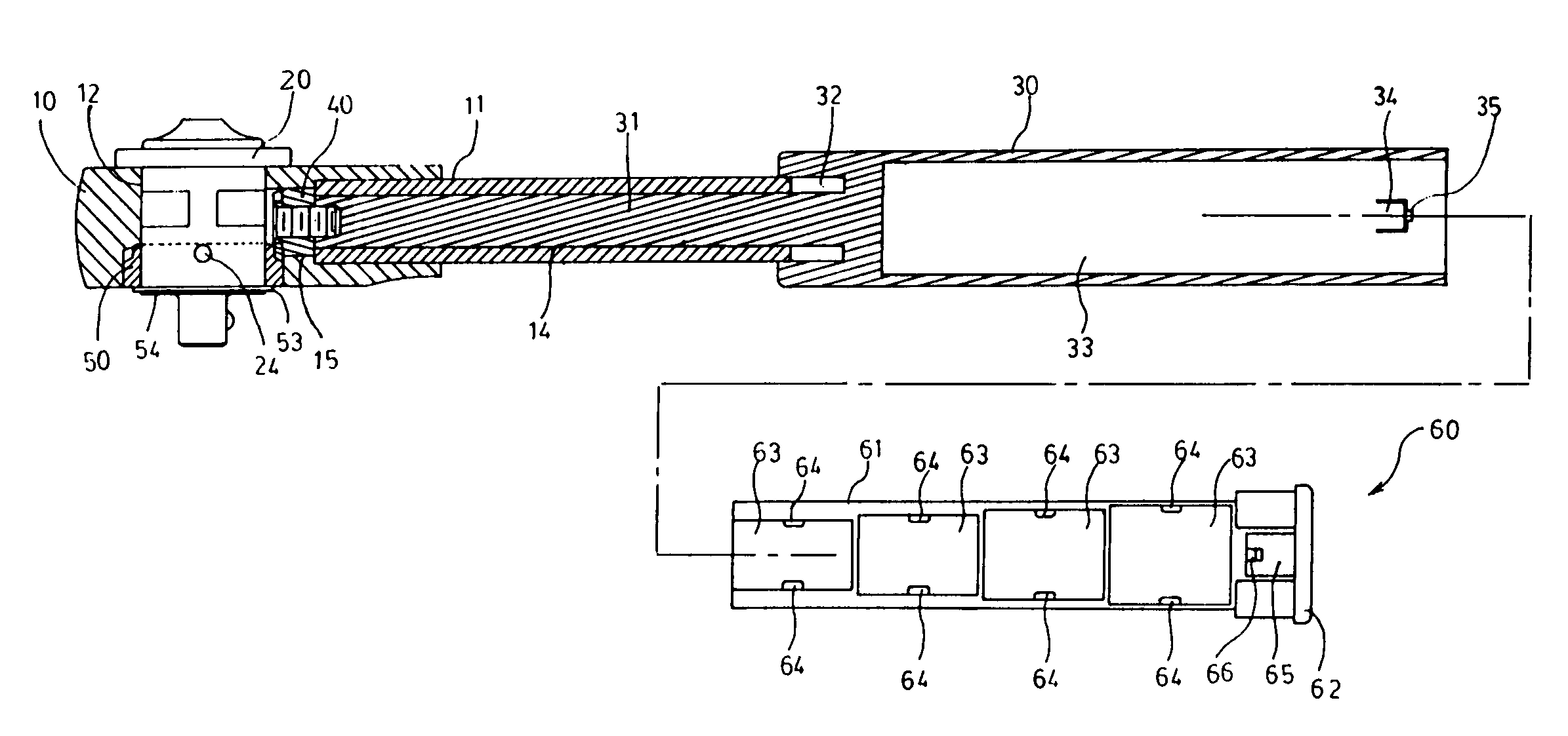
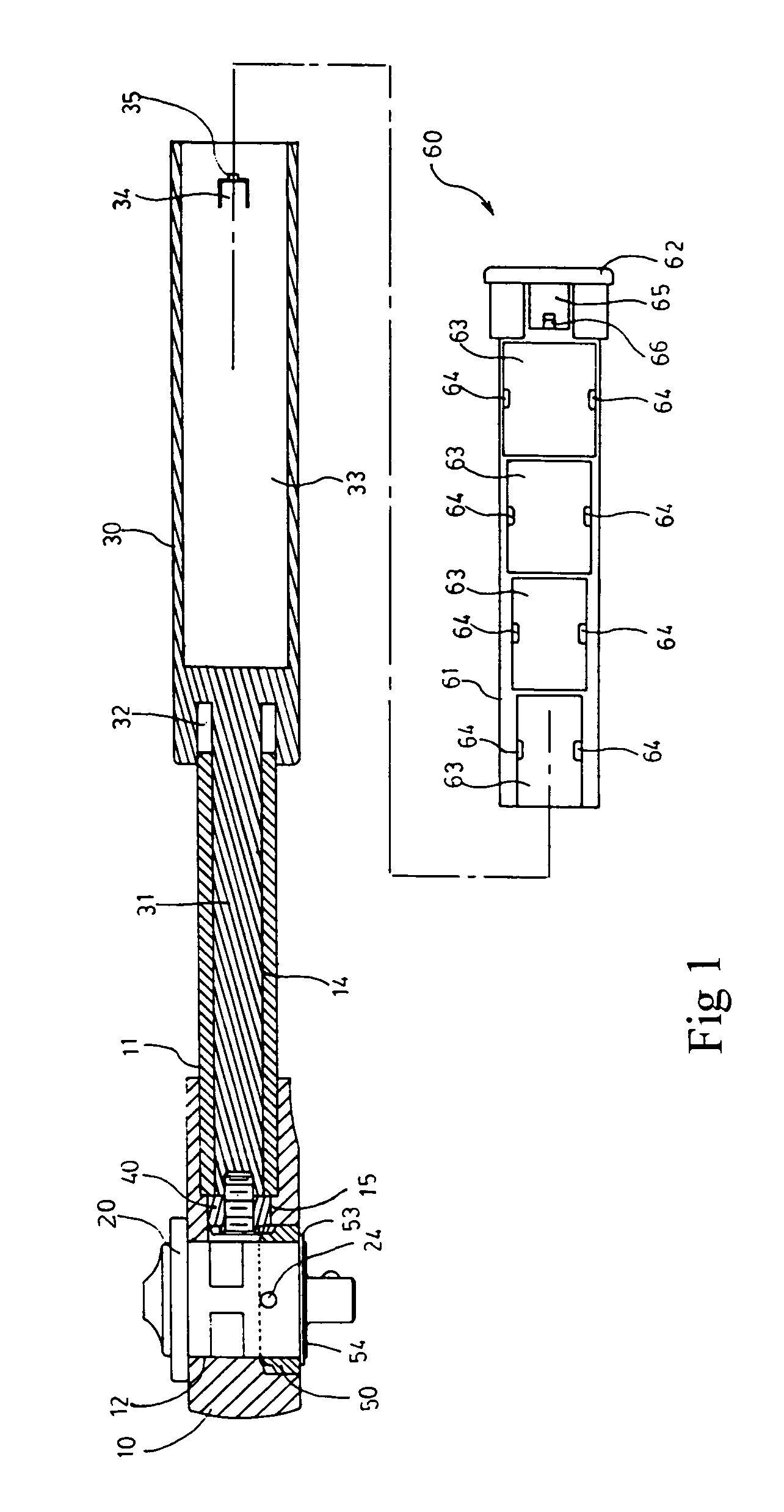
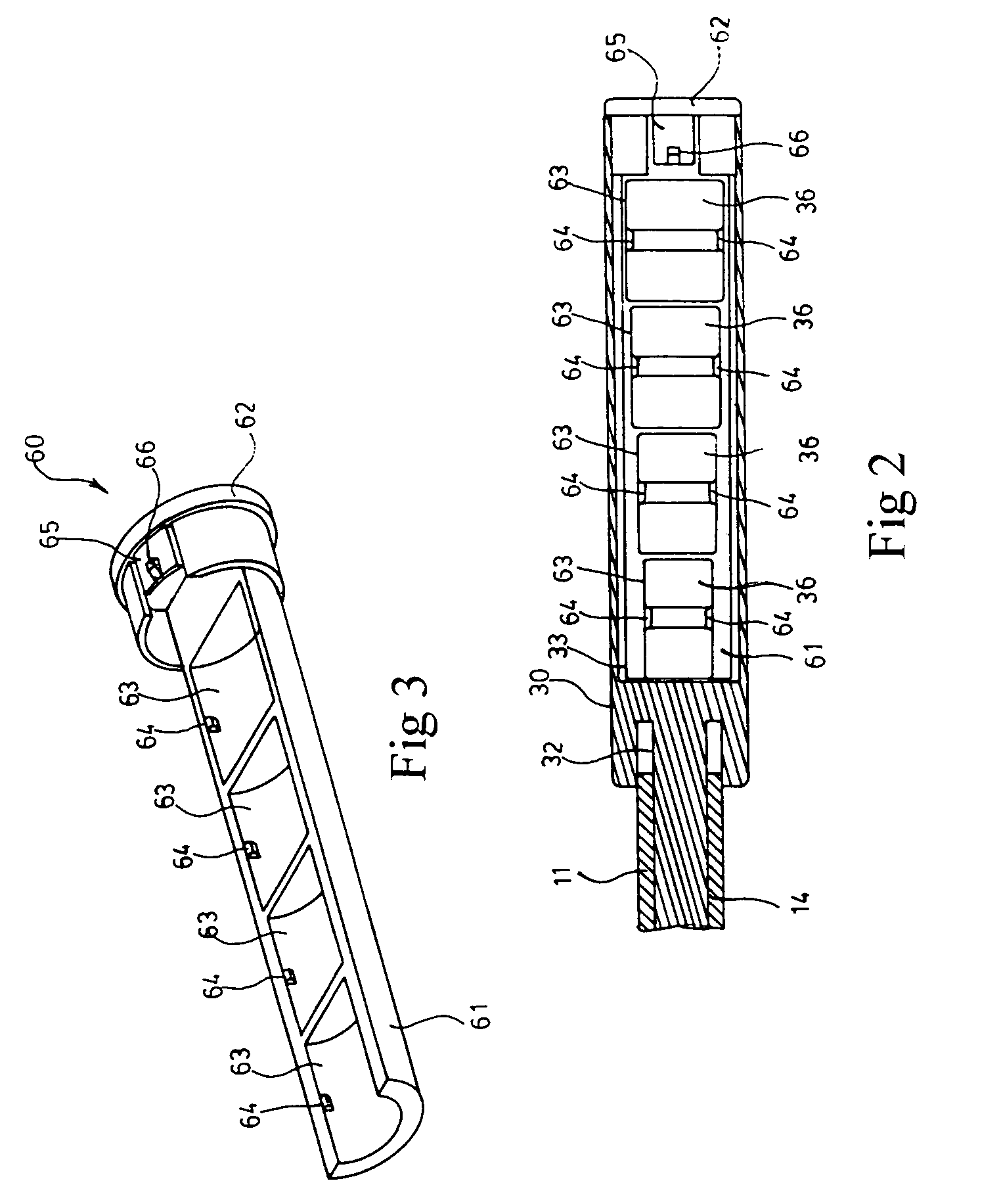
[0007]The handle collecting structure for socket wrench of the current invention includes a formed-in-one-piece handle and rotating rod to let a chamber be formed inside the handle so that a pending platform can be inserted and collected inside it. The pending platform is comprised of a semi-circular long rod seat body and cover part which are formed in one piece. Some slot seats of different dimensions are installed at the inside of the seat body to be embedded and positioned by sockets of different dimensions. When the pending platform is inserted into the chamber of the handle by the seat body end, its cover part end can then cover the chamber end. Some sockets can then be conveniently and stably collected inside the handle and become easy to be taken out for use.

Problems solved by technology

The socket wrench of the prior art can only provide a basic reciprocating stroke function.

Method used


Image

  • Handle collecting structure for socket wrench
  • Handle collecting structure for socket wrench
  • Handle collecting structure for socket wrench

Examples


Embodiment Construction

[0011]In order to help one understand the technical means adopted by the current invention and make its function more apparent, a first embodiment accompanied with the drawings is described in the following:

[0012]Please refer to FIG. 1. The socket wrench structure of the current invention basically is the same as the prior art U.S. Pat. No. 6,718,850 B2 “TORQUE TRANSFER MECHANISM FOR SOCKET WRENCH”. That is, handle 30 has a rotating rod 31 that penetrates into pivoting hole slot 14 of a handle part 11, through the end an indented flash slot 32 of handle 30 provide a space for the handle part 11 to enter. Therefore, the front end of the rotating rod 31 can extend into a chamber 12 of a head end part 10 of the wrench main body to facilitate the locking of an oblique gear 40 onto the front end of the rotating rod 31. Meanwhile, after locking is completed, oblique gear 40 is pulled back to the open chamber 15. Furthermore, a rotating head 20 is placed inside the chamber 12 through a top...


PUM


Abstract

A socket storage arrangement for a socket wrench includes a handle having an accommodating chamber formed therein. A pending platform includes a semi-cylindrical long rod seat body which is removably insertable into the accommodating chamber. The seat body is formed with a plurality of separated slot seats each having a different dimension for respectively accommodating a different sized socket. The seat body further includes a plurality of projecting pivoting pieces, each being formed on a side wall of a respective slot seat. Each projecting pivoting piece projects radially into the accommodating chamber, and presses against a respective socket received within the respective slot seat, to retain the socket within the slot seat.

Description

BACKGROUND OF THE INVENTION[0001]1. Field of the Invention[0002]This invention relates to a handle collecting structure for a socket wrench. This structure improves the collecting mode of the U.S. Pat. No. 6,684,738B2, and also improves the stiffness between the handle and the rotating rod. Meanwhile, it is also a structure having a handle which can collect some sockets neatly and is very convenient to use.[0003]2. Description of the Prior Art[0004]The prior art socket wrench usually has a head part of a wrench body extending horizontally. In a one-piece handle part of an appropriate length, there is a vertically oriented round chamber to be inserted by a rotating head. Through a tooth installed at the inner wall of the chamber, and a corresponding protecting piece installed at the two sides of the rotating head, when an adjustment knob on top of the rotating head is operated to select right or left rotation, it can trigger a change on one side of the projecting piece which protrude...

Claims


Application Information

Patent Timeline
Patent Type & Authority Patents(United States)
IPC IPC(8): B25B23/16B25G1/08B25G3/18F16B21/00F16D1/00
CPCB25B13/461B25G1/085Y10T403/606
Inventor HUANG, CHIN-CHEN
Owner HUANG CHIN CHEN
Learn More