Portal for a communications system

Inactive Publication Date: 2007-02-06
INTERDIGITAL MADISON PATENT HLDG
View PDF10 Cites 452 Cited by
  • Summary
  • Abstract
  • Description
  • Claims
  • Application Information

AI Technical Summary

Benefits of technology

[0005]The systems and methods described herein relate to a portal for simultaneously viewing video channels, launching interactive applications, and/or interfacing with locally or remotely stored content. The portal is the user's “home base” from which he/she can navigate to the different features within the system. The portal is based

Problems solved by technology

While the ability to communicate more information offers many opportunities, it b

Method used


Image

  • Portal for a communications system
  • Portal for a communications system
  • Portal for a communications system

Examples


Embodiment Construction

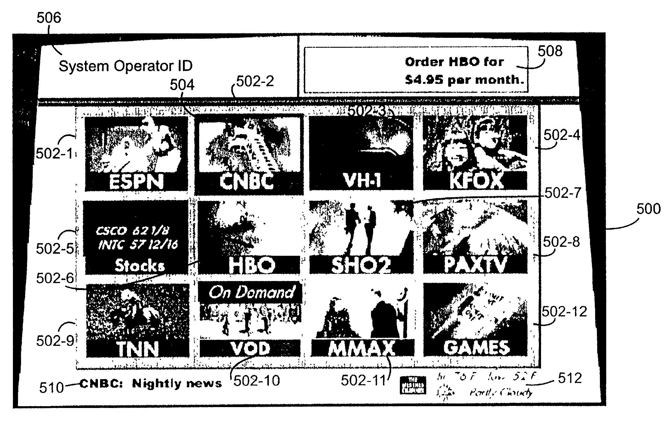
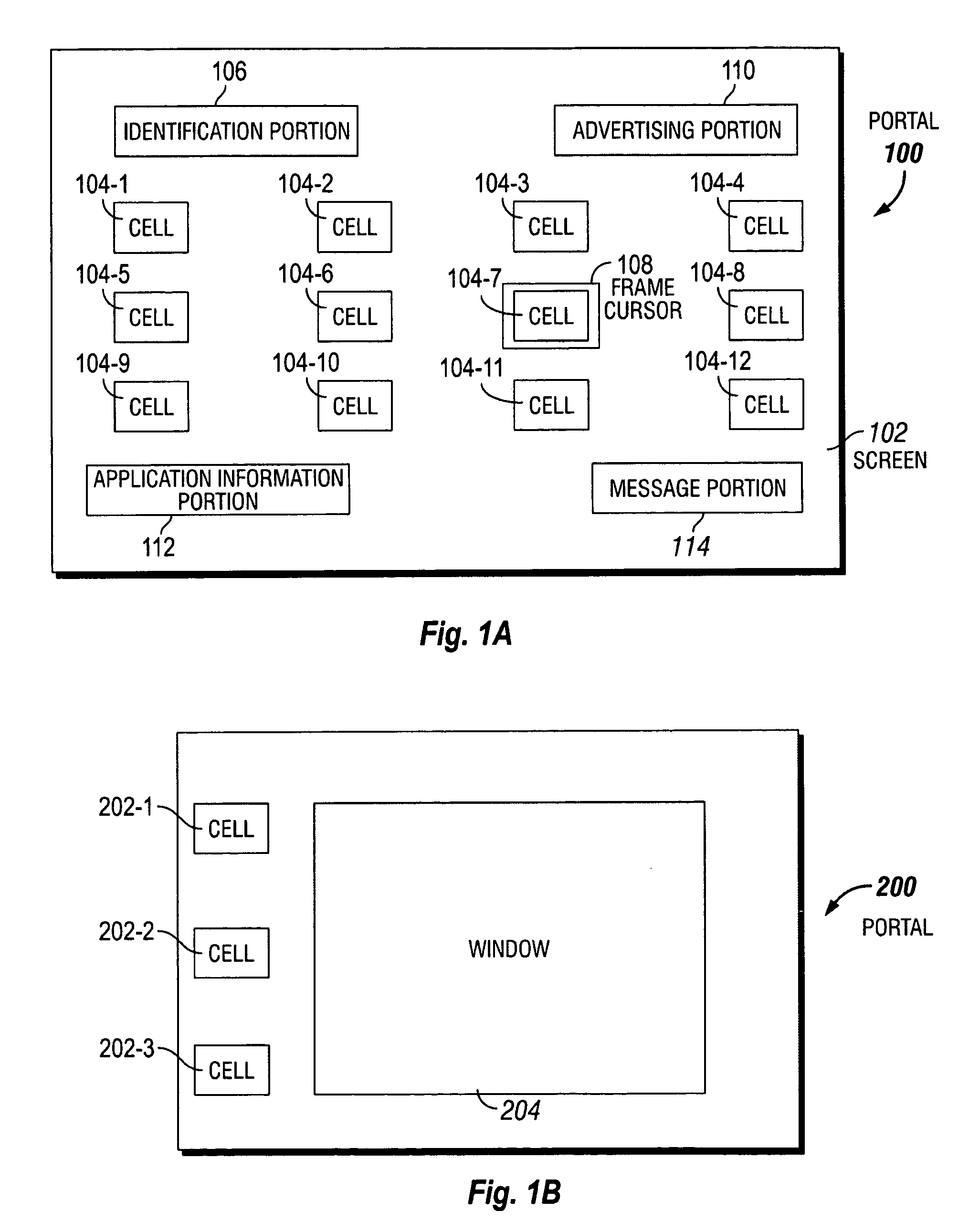
[0024]FIG. 1A shows an example portal 100. Portal 100 is displayed on a display such as a television. Example portal 100 provides access to various services offered in a television system (e.g., a digital television system) and comprises “cells”104-1 to 104-12 arranged in a row and column matrix on a television screen 102. In the example portal, the twelve cells are arranged in a 3-row by 4-column matrix. Of course, the invention is not limited to any particular number of cells or even to a row and column arrangement. Additionally, there is no requirement that each cell be of the same size. Each cell 104 has associated therewith a visual object and an underlying application. The visual object preferably provides a readily recognizable representation of the underlying application and may, by way of example, be in the form of live video from a television channel, a video loop (e.g., a preview from an upcoming television show or movie), a still video image, a graphic, text or some comb...


PUM


Abstract

A portal for a communications system that includes a remote terminal connected via a communications network to a broadcast center. The portal includes a display connected to the remote terminal for displaying an arrangement of cells, each cell including a visual object and an underlying application. A user input device enables user inputs to select one of the cells. The portal provides simple and intuitive access to the wide variety of services currently offered, and to be offered in the future, in communications systems.

Description

CROSS-REFERENCE TO RELATED APPLICATIONS[0001]This patent application is related by subject matter to PCT / IB99 / 01356, entitled “Navigation System for a Multichannel Digital Television Signal”, and to PCT / IB99 / 01350, entitled “Navigation System for a Multichannel Digital Television Signal”. The entire contents of these documents are incorporated herein by reference. This application claims the benefit of U.S. Provisional Patent Application No. 60 / 250,350 filed Dec. 1, 2000.FIELD OF THE INVENTION[0002]The present invention generally relates to a communications system and, more particularly, to a portal that provides simple and intuitive access to the wide variety of services currently offered, and to be offered in the future, in communications systems such as digital television systems.BACKGROUND OF THE INVENTION[0003]As the bandwidth of communication systems increases, more and more information can be communicated to users that are connected in and to these systems. While the ability ...

Claims


Application Information

Patent Timeline
IPC IPC(8): G11B27/00G06F3/00H04N21/4725G06Q30/02H04H60/47H04H60/65H04N5/50H04N7/08H04N7/081H04N21/431H04N21/482
CPCG06Q30/02H04N21/8547H04N5/4401H04N5/44543H04N21/4312H04N21/4314H04N21/4622H04N21/4627H04N21/47202H04N21/47815H04N21/482H04N21/4886H04H60/65H04N5/45H04N5/50H04N21/42204H04N21/4316H04N21/47H04N21/478H04H60/47H04N21/426
Inventor MARTIN, CHRISTY R.AGASSE, BERNARD
Owner INTERDIGITAL MADISON PATENT HLDG
Why Eureka
Try Eureka