
Side-entry lamping fixture

Inactive Publication Date: 2007-02-13
PHILIPS LIGHTING NORTH AMERICA CORPORATION
View PDF10 Cites 20 Cited by
  • Summary
  • Abstract
  • Description
  • Claims
  • Application Information

AI Technical Summary

Benefits of technology

[0010]With regard to the foregoing, the present invention eliminates the oversights, difficulties, and disadvantages of the prior art by providing a side-entry lamping fixture.
[0014]It is still an even further object of the present invention to a track lighting fixture having a lamping cartridge which is removable from a side of the fixture and allows for linear installation and removal of a lamp from a socket without interference with the reflector and fixture.
[0015]More specifically, the present invention provides a side-entry lamping fixture and cartridge, comprising a fixture having an upper fixture wall and a lower fixture wall, first and second sidewalls joining said upper and lower fixture walls and, at least one of the first and second sidewalls having a re-lamping aperture. The apparatus further comprises a lamping cartridge having a cover including a socket attached to the cover, a lamp in electrical communication with the socket and a fastening portion extending from the cover. The fixture and cartridge provide for a removable unit containing a fixture lamp which may be replaced without interfering with the fixture walls or a reflector therein, yet remain properly oriented when installed.

Problems solved by technology

During development, applicant's side-mounted lamp exhibited two problems.
First, the lamp or arc tube was prone to breakage during installation and removal of old lamps.
Otherwise stated the fixture did not provide for enough linear clearance between the socket and the reflector opposite the socket for the length of the arc tube and pins.
As a result, when the lamp was initially installed in the fixture, the lamp had to be angled for installation into the socket and the lamp pins were often broken during installation into the socket.
In addition, the lamp often struck the reflector which scratched the reflector and / or broke the lamp glass resulting in injury to the installer.
On the other hand, when an expired lamp was removed from the socket the lack of linear clearance for the lamp and pin between the socket and opposed reflector wall also resulted in the lamp being removed at an angle and either breakage of the lamp pins or interference between the lamp and the reflector.
This also resulted in scratches on the reflector and / or broken lamp glass.

Method used


Image

  • Side-entry lamping fixture
  • Side-entry lamping fixture
  • Side-entry lamping fixture

Examples


Embodiment Construction

[0020]Given the foregoing deficiencies, it will be appreciated that a side-entry lamping cartridge is needed for use with a track lighting fixture which allows for removal of the lamp without damaging the lamp, fixture, or reflector therein.

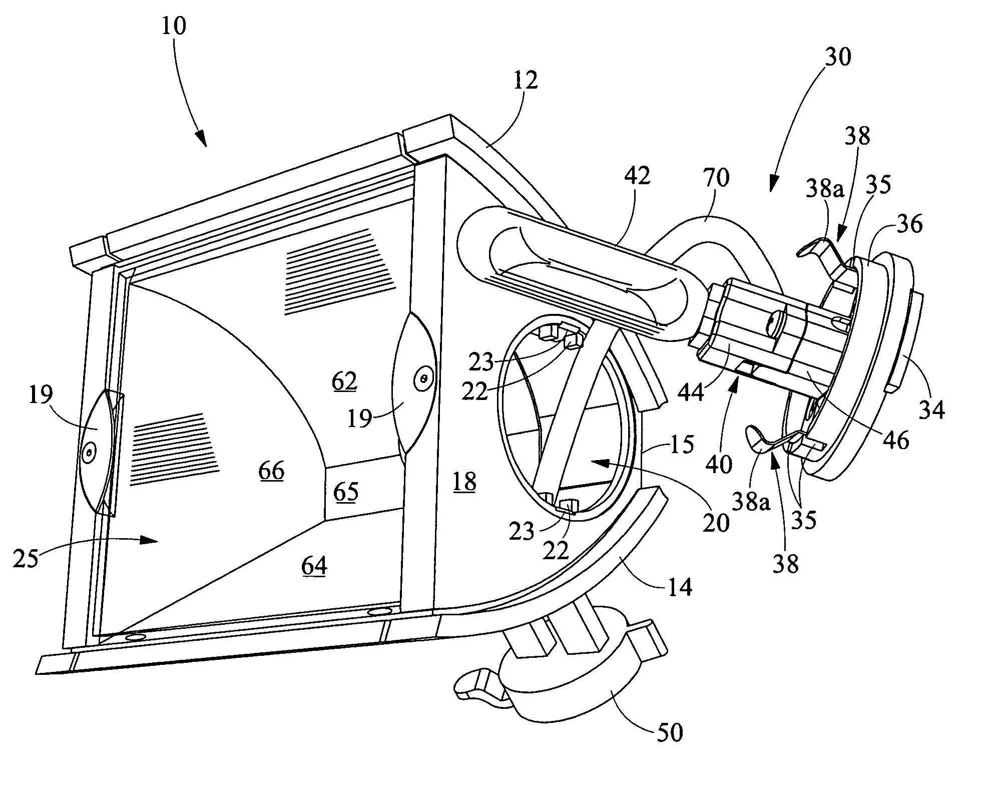
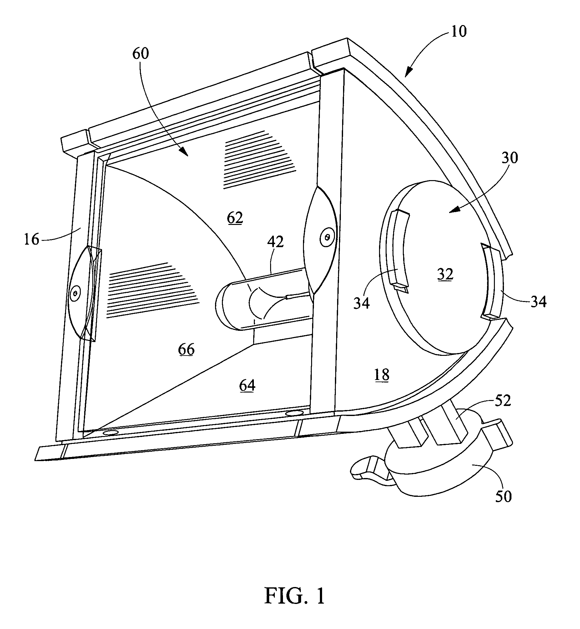
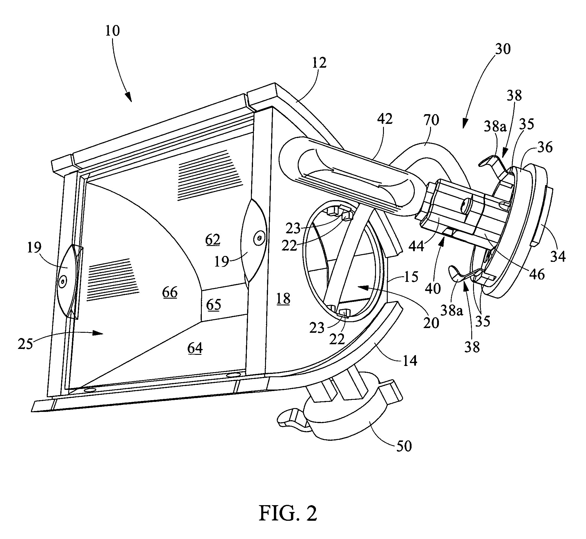
[0021]Referring now in detail to the drawings, wherein like numerals indicate like elements through out the several views, there is shown in FIGS. 1–4 various aspects of a side-entry lamping fixture of the present invention. The side-entry lamping fixture of the present invention overcomes problems associated with the prior designs by utilizing a lamping cartridge which may be removed from a fixture sidewall in order to change lamps and precludes the need for a larger fixture for the preselected lamp size.

[0022]Referring initially to FIG. 1, a side-entry lamping fixture 10 is shown in a perspective view. The illustrative side-entry lamping fixture 10 of the present invention may be utilized on a tracklight system in order to provide a wall wash f...


PUM


Abstract

The present invention provides a side-entry lamping fixture and cartridge, comprising a fixture having an upper fixture wall and a lower fixture wall, first and second sidewalls joining said upper and lower fixture walls and, at least one of the first and second sidewalls having a re-lamping aperture. The apparatus further comprises a lamping cartridge having a cover including a socket attached to the cover, a lamp in electrical communication with the socket and a fastening portion extending from the cover. The fixture and cartridge provide for a removable lamp which may be replaced without interfering with the fixture walls or a reflector therein, yet remain properly oriented when installed.

Description

CROSS REFERENCES TO RELATED APPLICATIONS[0001]None.STATEMENT REGARDING FEDERALLY SPONSORED RESEARCH OR DEVELOPLMENT[0002]None.REFERENCE TO SEQUENTIAL LISTINGS, ETC.[0003]NoneBACKGROUND[0004]1. Field of the Invention[0005]The present invention comprises a high intensity discharge fixture for a track lighting system. More specifically, the present invention provides a high intensity discharge lamp and fixture having a side-entry lamping cartridge for a track lighting system.[0006]2. Description of the Related Art[0007]Applicant's present invention is related to a fixture for a track lighting system. Applicant's present invention is derived from an attempt to develop a fixture having a side-mounted lamp installation which is utilized with a track lighting system.[0008]During development, applicant's side-mounted lamp exhibited two problems. First, the lamp or arc tube was prone to breakage during installation and removal of old lamps. Applicant's initial fixture was sized only slightly...

Claims


Application Information

Patent Timeline
IPC IPC(8): F21S4/00
CPCF21V19/008F21V15/015F21S8/038F21V19/04F21Y2103/00
Inventor MEDEIROS, ANDREW E.
Owner PHILIPS LIGHTING NORTH AMERICA CORPORATION
Learn More