
Terminal fitting

a technology of fittings and fittings, applied in the direction of coupling contact members, coupling device connections, electrical devices, etc., can solve the problem of increasing the possibility of external matter entering the rectangular tube through these openings

Active Publication Date: 2007-02-13
SUMITOMO WIRING SYST LTD
View PDF8 Cites 2 Cited by
  • Summary
  • Abstract
  • Description
  • Claims
  • Application Information

AI Technical Summary

Benefits of technology

The invention is a terminal fitting with a tube that includes a base plate. The tube has a long narrow resilient contact that can contact a tab that enters the tube. The resilient contact has a bend that is continuous with the base plate, an extending portion that extends back from the bend, and a narrower base portion that is reinforced by a bulge that bulges out from a lateral edge of the base portion towards a side plate of the tube. This design prevents external matter from entering the tube through the opening and deformation of the base portion. The base portion is made narrower by cutting away one or more lateral edges of the base plate. The widthwise centers of the resilient contact and the base portion are deviated from the widthwise center of the tube. The bulge is formed only at the lateral edge opposite the side towards which the widthwise center of the base is deviated. The front edge of the bulge is oblique to the longitudinal direction of the resilient contact. The terminal fitting has a ceiling plate and pressing portion for preventing outward displacement of the ceiling plate. These features improve the reliability and durability of the terminal fitting.

Problems solved by technology

Thus, areas of openings between the base portion and the side plates become larger as the width of the resilient contact piece increases as against that of the rectangular tube, thereby increasing a possibility of the intrusion of external matter into the rectangular tube through these openings.

Method used


Image

  • Terminal fitting
  • Terminal fitting
  • Terminal fitting

Examples


Embodiment Construction

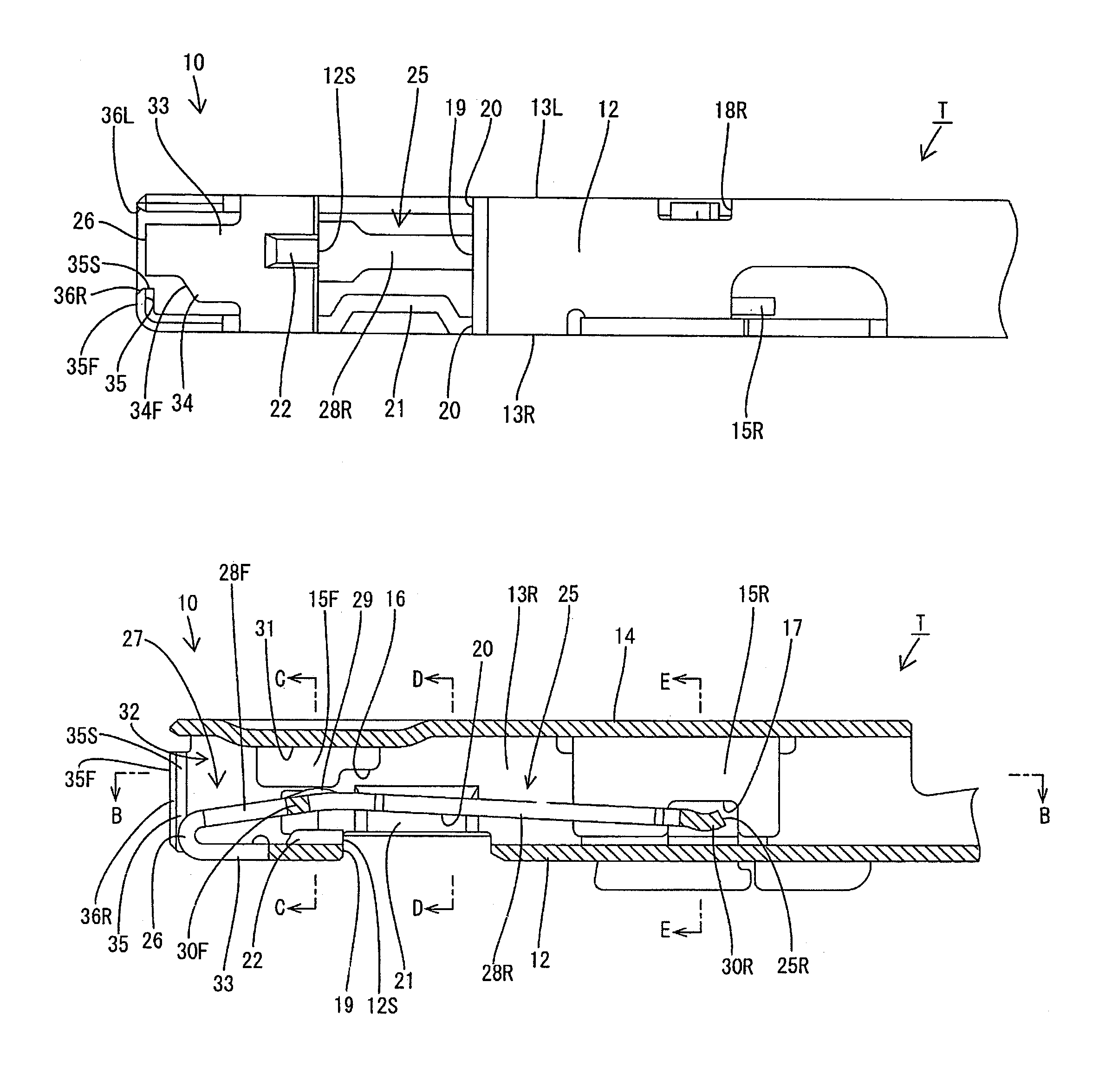
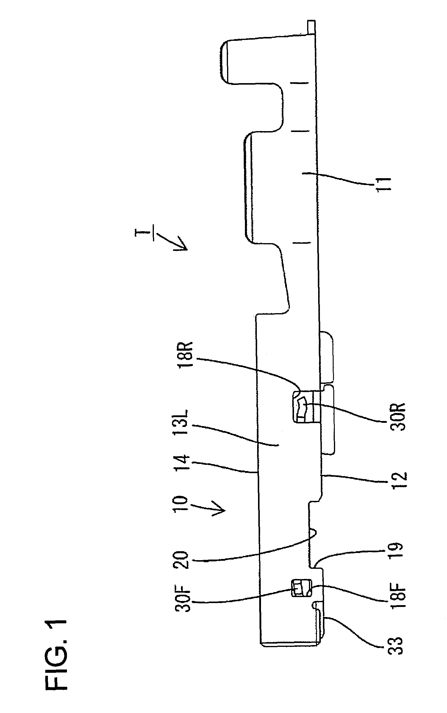
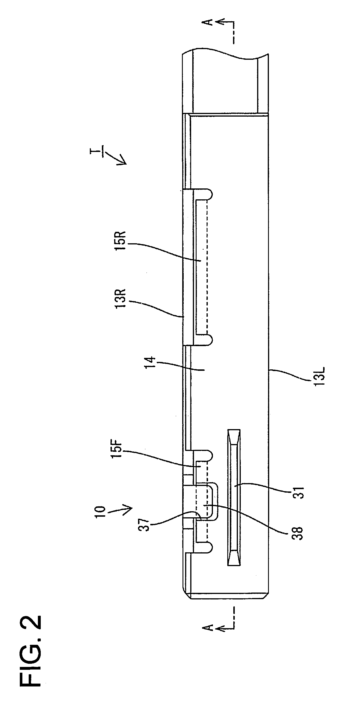
[0035]A terminal fitting according to the invention is identified by the letter T in FIGS. 1 to 18. The terminal fitting T is accommodated in a connector housing 50 that is made of a synthetic resin. Cavities 51 penetrate the housing 50 in forward and backward directions, and a lock 52 is cantilevered substantially forward along the bottom wall of each cavity 51. A retaining projection 52a is formed on the surface of each lock facing the cavity 51.

[0036]A front plate 53 is mounted on the front of the housing 50 and is movable vertically between a partial locking position and a full locking position. Tab insertion openings 55 and work openings 56 are formed in the front plate 53 at positions substantially corresponding to the respective cavities 51. The tab insertion openings 55 are slightly above centers of the cavities 51 and the work openings 56 are at positions substantially corresponding to locks 52 when the front plate 53 is at the full locking position, as shown in FIGS. 12 to...


PUM


Abstract

A terminal fitting (T) has a rectangular tube (10) with a bottom plate (12). A resilient contact (25) extends back into the tube (10) from an end of the bottom plate (12). A base portion (33) is formed at the front end of the bottom plate (12) and is made narrower than the bottom plate (12) by cutting away the left and right edges. A bulge (34) bulges out from a lateral edge of the base portion (33) and narrows an area of an opening between the base portion (33) and the right side plate (13R). Thus, external matter is less likely to intrude into the rectangular tube (10) through the opening even if the resilient contact (25) is narrow. Additionally, the base portion (33) is reinforced by the bulge (34). Thus, the base portion (33) is less likely to be deformed by external matter.

Description

BACKGROUND OF THE INVENTION[0001]1. Field of the Invention[0002]The invention relates to a terminal fitting.[0003]2. Description of the Related Art[0004]U.S. Pat. No. 5,235,743 discloses a terminal fitting with a rectangular tube that has a front opening into which a tab is insertable. A resilient contact is provided in the rectangular tube for contacting the tab. The resilient contact is long and narrow along forward and backward directions, and has an arcuate bend that extends continuously form the front end of a bottom plate of the rectangular tube. The resilient contact also has an extending portion that extends back from the bend, and is resiliently deformable with the bend as a support.[0005]A base portion narrower than the bottom plate is formed is formed in some terminal fittings of this type by cutting the left and right edges of a front end of the bottom plate. The bend of the resilient contact is continuous with the front end of the base portion and is easier to deform in...

Claims


Application Information

Patent Timeline
Patent Type & Authority Patents(United States)
IPC IPC(8): H01R13/15
CPCH01R13/113H01R43/16H01R13/422
Inventor NORO, YUTAKAISHIKAWA, RYOTAROKAWASE, HAJIMENAKAMURA, KEIICHIKOBAYASHI, YUTAKA
Owner SUMITOMO WIRING SYST LTD
Learn More