
Anti-loose screw with double-thread nut

A double thread and nut technology, applied in the direction of nuts, threaded fasteners, screws, etc., can solve the problems of the nut anti-loosening interval becoming smaller, the reverse nut loosening, and the connector cannot be inserted into the connector, so as to reduce the number of accessories. , The effect of preventing the nut from loosening and reducing the accumulation of loose space

Pending Publication Date: 2022-02-22
钟振贤
View PDF2 Cites 0 Cited by
  • Summary
  • Abstract
  • Description
  • Claims
  • Application Information

AI Technical Summary

Problems solved by technology

The inventors have found that the existing disadvantages are as follows: 1. The nut can only work normally at the junction of the complete thread section of the notch and the bolt. When the length of the nut screwed into the bolt is greater than the length of the notch, the connector It cannot be tightly connected with the nut, so the connector loses the anti-loosening effect on the nut
2. The connector can only be engaged with the second conflicting part on the nut when the second conflicting part of the nut is just rotated to the position aligned with the notch. When the slots are not aligned, the connector cannot be engaged with the second conflicting part
When the rotation of the second conflicting part exceeds or may not be in place, the connector cannot be inserted or the connection is not tight, and a relatively large loosening area appears. In practice, this kind of anti-loosening screw can only prevent falling off but not loosening.
3. Due to the long notch on the screw, the strength and elasticity of the screw are seriously affected, and the anti-loosening performance of the nut is also seriously damaged.
The present inventor finds that the weak point that it exists has: 1. the connection of nut cover and nut is longitudinal groove connection, can not effectively prevent the outward loosening of nut cover on the one hand, on the other hand nut cover prevents the nut from being loose. Insufficient loosening ability
Any relying on elastic components to prevent loosening in a strong vibration working environment cannot be effective and durable
3. Due to the structural defect of the concave groove of the nut sleeve, it is difficult to realize the precise socketing of the nut sleeve with the forward nut and the reverse nut at the same time, which will inevitably lead to the retreat and loosening of the reverse nut in actual work, plus The nut sleeve is connected in series with the forward nut and the reverse nut at the same time, resulting in a relatively large accumulation of loosening intervals, and a larger loosening space for the forward nut
4. The longitudinal position of the clamping groove on the nut sleeve is fixed, so the tightened section of the forward nut is limited by the length of the reverse thread section on the screw rod, the nut sleeve cannot move independently, and the nut loosening section becomes variable. Small, unable to adapt to the diversity of fasteners
[0007] It can be seen that there are still defects in the existing nut anti-loosening structure, and it is necessary to make further innovations and improvements to the existing nut anti-loosening structure

Method used


Image

  • Anti-loose screw with double-thread nut
  • Anti-loose screw with double-thread nut
  • Anti-loose screw with double-thread nut

Examples


Embodiment 1

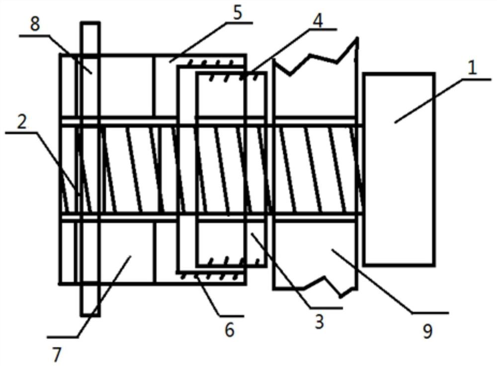
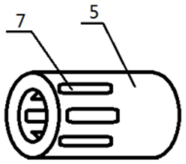
[0046] Such as Figure 1-12 As shown, a kind of anti-loosening screw adopting double-threaded nuts includes a screw rod 1, a nut 3 and a sleeve 5; one end of the sleeve 5 is threadedly connected with the nut 3; the screw rod 1 is screwed with the nut 3, and extends To the other end of the sleeve 5, this end is engaged with the screw rod 1 in a movable manner.

[0047] Way of working:

[0048] The screw goes through the fastened part 9 from one side of the fastened part 9, and is threaded with the nut 3. When the nut 3 is screwed into the screw 1 to reach the required position, the sleeve 5 is sleeved on the screw 1 and connected with the nut 3. screwed connection, and then the screw rod 1 is engaged with the sleeve 5 . The snap-fit ​​connection prevents the sleeve 5 from rotating, and the sleeve 5 prevents the nut 3 from rotating, thereby achieving the purpose of preventing the screw from loosening.

[0049] When the fastener 9 vibrates, the fastener 9 transmits the vibrati...

Embodiment 2

[0052] Compared with Embodiment 1, the difference is that: a connection mode of the nut 3 and the sleeve 5 is provided.

[0053] Such as figure 1 As shown, the connection method is screw connection. The assembly and disassembly between the nut 3 and the sleeve 5 can be facilitated, and the sleeve 5 can be prevented from loosening along the axial direction.

Embodiment 3

[0055] Compared with Embodiment 1 or 2, the difference is that: a screw connection structure of the nut 3 and the sleeve 5 is provided.

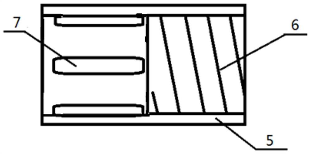
[0056] Such as figure 1 and 2 As shown, a first thread 4 and a second thread 6 are added; the first thread 4 is provided on the outer surface of the nut 3; the second thread 6 is provided on the inner surface of one end of the sleeve 5; wherein, the sleeve The barrel 5 and the nut 3 are screwed together with the first thread 4 through the second thread 6 .

[0057] Such as Figure 6 and 7 As shown, the outer side of the nut 3 is provided with a first thread 4, and its inner side is provided with an internal thread. Therefore, the nut 3 has double threads, which can apply two different rotational forces to the nut 3 from the inside and the outside at the same time, further improving the nut. anti-loosening effect.

[0058] The outer surface of the sleeve 5 and the thread 3 is threadedly connected; thus, the movable space of the sleeve 5 ...


PUM


Abstract

The invention discloses an anti-loose screw with a double-thread nut. The anti-loose screw comprises a screw rod, the nut and a sleeve. One end of the sleeve is in threaded connection with the nut; and the screw rod is screwed with the nut and extends to the other end of the sleeve, and the end is movably clamped and connected with the screw rod. The anti-loose screw has the characteristics of large anti-loosening interval, precision, reliability and the like.

Description

technical field [0001] The invention relates to an anti-loosening screw adopting a double-threaded nut. Background technique [0002] Bolts are cylindrical threaded fasteners that mate with nuts. A type of fastener consisting of a head and a screw (a cylinder with external threads), which needs to be matched with a nut to fasten two parts with through holes. It is more common to use bolted connections in mechanical equipment. [0003] Vibration, shock, temperature changes and other causes of mechanical equipment during operation will affect the fastness and reliability of threaded connections. Therefore, preventing the nut from loosening is the key to ensure the normal operation of the equipment. The common way to lock nuts is to lock them with double nuts. The double nuts are divided into main nuts and auxiliary nuts. However, the anti-loosening effect of this method is not ideal; Between the nut meshing teeth, a corresponding compression force is generated due to the e...

Claims


Application Information

Patent Timeline
IPC IPC(8): F16B39/12F16B39/28F16B37/00F16B35/04F16B35/00
CPCF16B39/12F16B39/28F16B37/00F16B35/041F16B35/00
Inventor 钟振贤
Owner 钟振贤
Learn More