Vehicle height adjustment device and vehicle height adjustment method

a technology of height adjustment device and vehicle, which is applied in the direction of loading/unloading vehicle arrangment, transportation items, wound springs, etc., can solve the problems of complex construction of height adjustment device, a number of manufacturing steps or manufacturing process, and the manufacture process of such a vehicle height adjustment device requires a number of manufacturing steps or manufacturing processes, so as to reduce the number of parts or members, the effect of simplifying the construction of the devi

Inactive Publication Date: 2009-12-15
ISUZU MOTORS LTD
View PDF25 Cites 82 Cited by
  • Summary
  • Abstract
  • Description
  • Claims
  • Application Information

AI Technical Summary

Benefits of technology

[0015]Therefore, according to the present invention, the rotation of the spring seat associated with the rotation of the bolt can be restricted without structural separation of the bolt from the spring seat, and the spring seat holder can be eliminated to simplify the construction of the device and to reduce the number of parts or members of the device.
[0016]In a preferred embodiment of the present invention, the spring seat member is provided with a recess with an internal thread (female thread) formed therein, and the adjustment bolt has a screw part to be inserted into the recess. The screw part is provided with an external thread (male thread) threadedly engageable with the internal thread of the recess. Preferably, a diameter of the screw part is set to be greater than that of the shank of the bolt fixedly mounted on the wheel-side or vehicle-body member. More preferably, the core section of the spring seat member formed with the recess extends into a hollow inside area of the compression coil spring. In the core section, the recess is formed with the internal thread having a sufficient screw length. If such diameter and length of the screw are ensured, the spring seat member can be further stabilized.
[0017]Preferably, the adjustment bolt has a large-diameter screw part threadedly engaging with the aforementioned recess; a shank with a relatively small diameter connected to or continuous with the large-diameter screw part; a small-diameter screw part connected to or continuous with the shank; and rotating tool engagement means provided on an end portion of the small-diameter screw part. The large-diameter screw part, shank, small-diameter screw part and rotating tool engagement means are aligned with one another on an axis of rotation of the bolt. The shank is inserted through a through-hole formed in the wheel-side member or the vehicle-body member. The small-diameter screw part extends from the wheel-side or vehicle-body member on a side opposite to the spring. A screw-engaging member, such as a nut, threadedly engages with the small-diameter screw part. The bolt is fastened to the wheel-side or vehicle-body member by tightening the screw-engaging member and is rotated when the screw-engaging member is loosened or released. After the screw-engaging member is loosened or released, a rotating tool is engaged with the aforementioned engagement means. The bolt is rotated by the tool, whereby the spring seat member can be moved in an axial direction of rotation. If such an arrangement is applied to the bolt for the lower seat member, the vehicle height can be adjusted from the underside of the suspension system. This improves operability of the vehicle height adjustment. Such an arrangement allows the adjustment operation to be performed in the space below the suspension system, and therefore, works for the vehicle height adjustment are relieved. It is useful, particularly in a cab-over type truck which has a cockpit or the like located above the suspension system.
[0018]More preferably, a boss portion having the aforementioned through-hole is formed in the wheel-side member or the vehicle-body member. An annular journal surface can be provided on the adjustment bolt by a step formed in a transition between the large-diameter screw part and the small-diameter shank. It is desirable that the boss portion has a flat bearing surface abutting against this annular journal surface. Fixation of the bolt is further stabilized where the annular journal surface is seated on the bearing surface, and therefore, the positions of the large-diameter screw part and the spring seat member can be more precisely controlled and stabilized.
[0033]According to such an arrangement of the present invention, displacement of the spring seat member can be caused in the axial direction of rotation of the adjustment bolt by rotation of the bolt. The relative displacement between the spring seat member and the bolt occurs so as to move toward each other in the axial direction of rotation when a tightening torque is applied to the bolt, whereas it occurs so as to move apart from each other in the axial direction of rotation when a loosening torque is applied to the bolt. According to such a method for adjusting a vehicle height, a vehicle height adjustment mechanism can be provided in the suspension system by provision of the bolt on the wheel-side or vehicle-body member, suitable design of the position and shape of the component of the wheel-side or vehicle-body member, and suitable design of the position and shape of the spring seat member. Therefore, the construction of the vehicle height adjustment mechanism can be considerably simplified.

Problems solved by technology

However, a resilient repulsive force of a compression coil spring, which is not rotatable, normally acts on the spring seat.
Thus, a manufacturing process of such a vehicle height adjustment device requires a number of manufacturing steps or a complicated manufacturing process.
As a result, such a type of vehicle height adjustment device requires a complicated construction of the device and a number of parts or members for the device.

Method used


Image

  • Vehicle height adjustment device and vehicle height adjustment method
  • Vehicle height adjustment device and vehicle height adjustment method
  • Vehicle height adjustment device and vehicle height adjustment method

Examples


Embodiment Construction

[0041]One preferred embodiment of the present invention is described in detail hereinafter, with reference to the accompanying drawings.

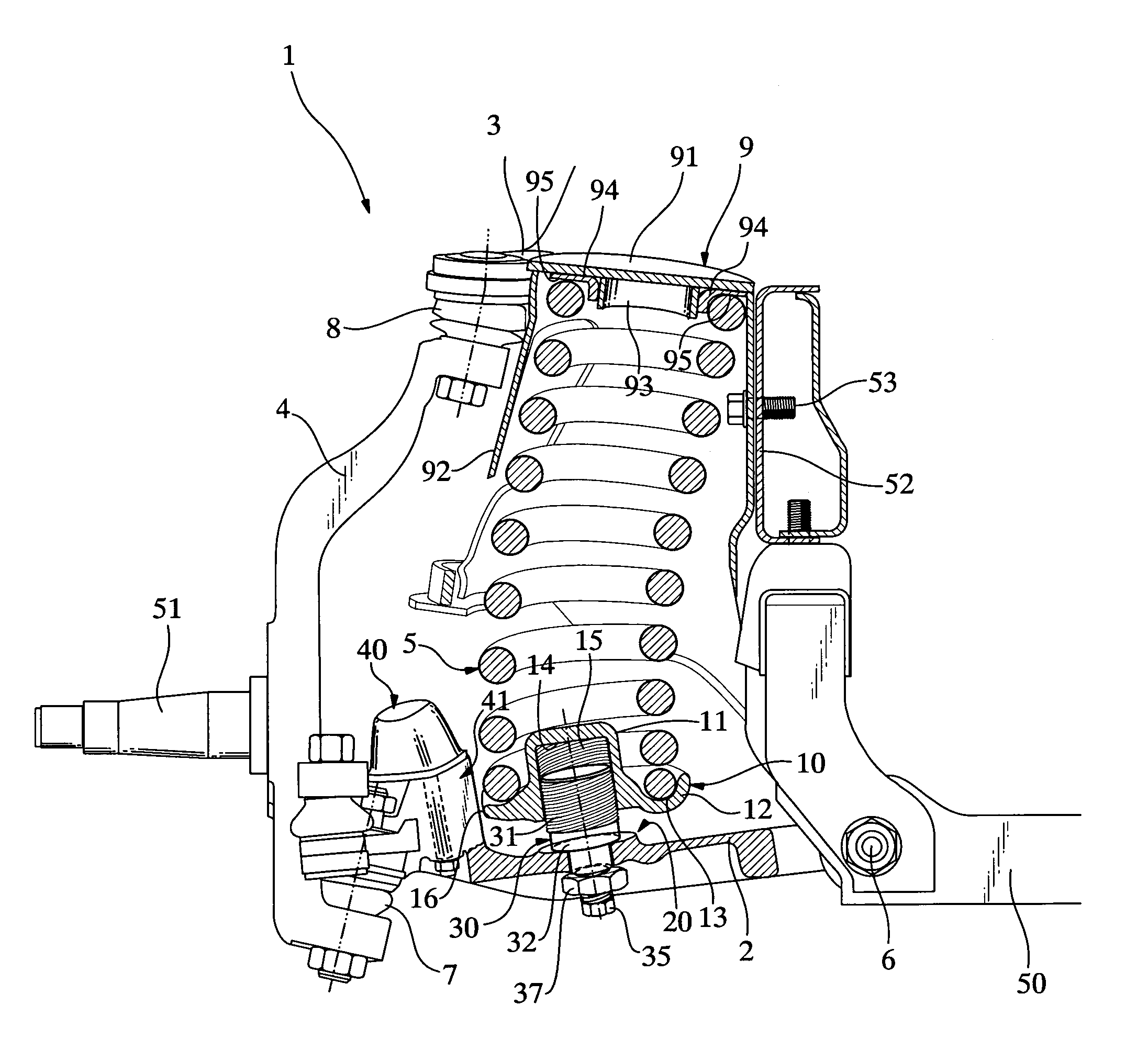
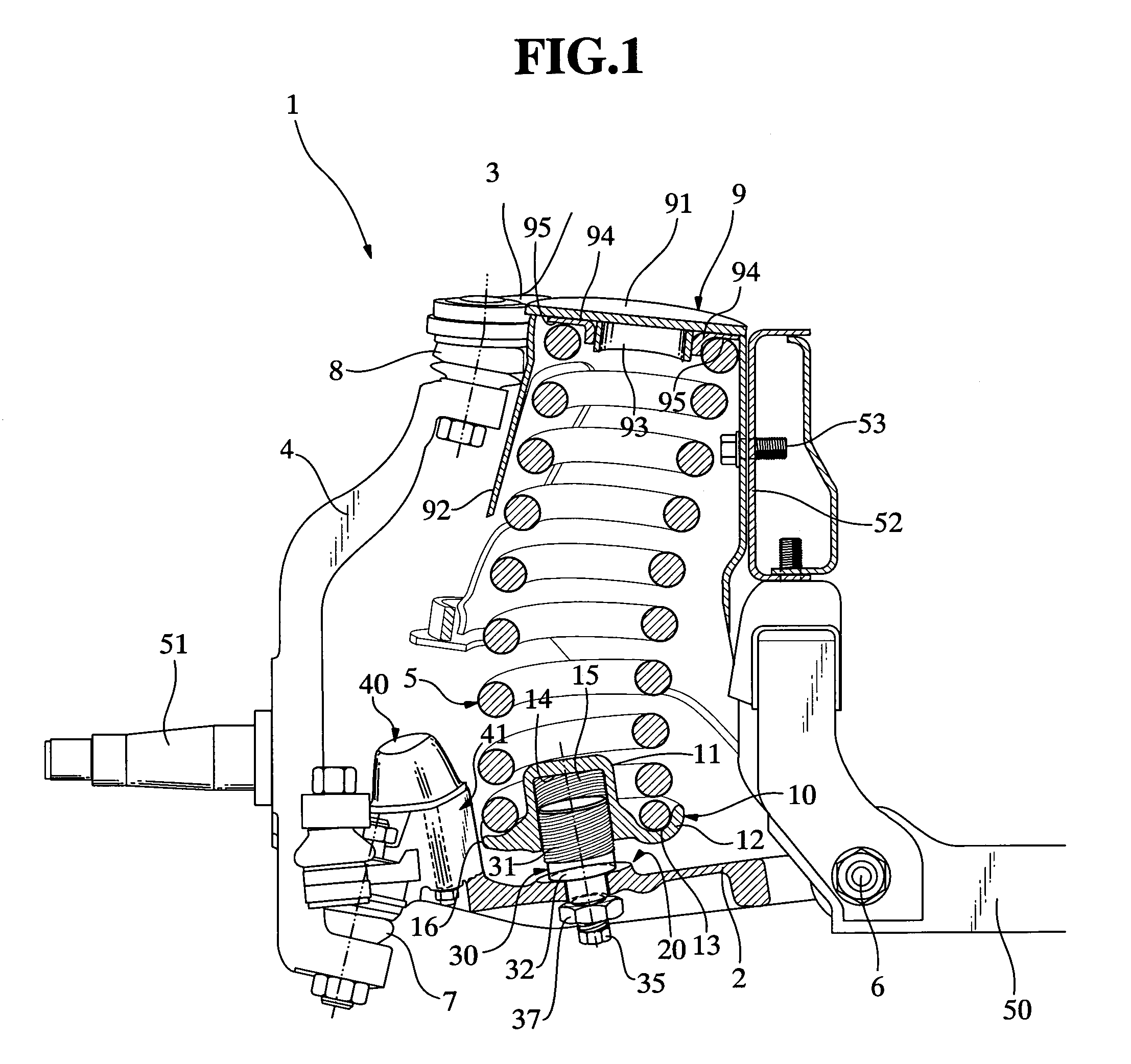
[0042]FIG. 1 is a partially cross-sectional side elevational view showing a construction of a main part of a vehicle suspension system provided with a vehicle height adjustment device according to the present invention, and FIGS. 2 and 3 are an enlarged cross-sectional view and an exploded cross-sectional view partially showing the device as shown in FIG. 1.

[0043]In FIG. 1, a main part of a double-wishbone-type suspension system (wheel suspension system) 1 is illustrated. The suspension system is provided with a lower arm 2, an upper arm 3, a knuckle 4 and a compression coil spring 5. One end portion of the lower arm 2 on a side of a vehicle body (an inner end portion) is swingably mounted on a vehicle-body member 50 by means of a pivot 6, whereas the other end portion of the lower arm 2 on a side of a wheel (an outer end portion) is articulated to ...


PUM


Abstract

A vehicle height adjustment device has an adjustment bolt (30) rotatably supported by or fixed to a wheel-side member or a vehicle-body member, and a spring seat member (10) threadedly engaging with the adjustment bolt. Rotation of the spring seat member is limited by a bump rubber pedestal (41) (or a coil spring bracket (9)). Displacement of the spring seat member occurs in an axial direction of rotation of the bolt, in accordance with rotation of the bolt. According to the present invention, rotation of the spring seat involved in rotation of the bolt for adjusting the vehicle height can be restricted, and a construction of a vehicle height adjustment mechanism can be simplified so that the number of parts or members of the device is reduced.

Description

[0001]This application claims the benefit of PCT International Application No. PCT / JP2005 / 008473 filed Apr. 27, 2005 and Japanese Application No. 2004-132582, filed Apr. 28, 2004 in Japan, the contents of which are incorporated herein by reference.TECHNICAL FIELD[0002]The present invention relates to vehicle height adjustment device and method for a suspension system, and more specifically, to such a device and method for adjusting the vehicle height by regulating a position of a spring seat member which abuts against an end portion of a compression coil spring interposed between a wheel-side member carrying a wheel and a vehicle-body member.TECHNICAL BACKGROUND[0003]A vehicle suspension system is known in the art, which has a compression coil spring interposed between a wheel-side member and a vehicle-body member, wherein upper and lower spring seats are provided for respectively supporting upper and lower end portions of the spring, and wherein a vehicle height adjustment device i...

Claims


Application Information

Patent Timeline
Patent Type & Authority Patents(United States)
IPC IPC(8): B60G17/00B60G11/16F16F1/12B60G17/02
CPCB60G11/16B60G17/021F16F1/121B60G2200/144B60G2204/61B60G2500/20B60G2500/30B60G2204/1244
Inventor HIRAO, SATOSHIKAWAHATA, SUSUMU
Owner ISUZU MOTORS LTD
Why Eureka
Try Eureka