
Substrate holding apparatus

a technology of holding apparatus and substrate, which is applied in the direction of electrical apparatus, clamps, and semiconductor devices, etc., can solve the problems of springs that may be broken before the expected lifetime of springs, springs that deform outwardly, and may be fatigued, so as to prevent unexpected spring breakage, prevent outward displacement of support posts, and avoid excessive stress

Active Publication Date: 2018-11-06
EBARA CORP
View PDF13 Cites 0 Cited by
  • Summary
  • Abstract
  • Description
  • Claims
  • Application Information

AI Technical Summary

Benefits of technology

This patent describes an improved substrate holding apparatus that minimizes deformation of a spring and prevents an outward displacement of the support post that holds a substrate. This is achieved through a structure that restricts the movement of the spring in response to centrifugal force, reducing stress and the risk of breakage, and ensuring the stability of the substrate during processing. Additionally, a coupling ring is used to prevent the support posts from displacing. This invention enhances the stability and reliability of the substrate holding apparatus.

Problems solved by technology

However, when the substrate is rotating at a high speed, strong centrifugal forces act on the springs disposed around the support ports, thus causing the springs to deform outwardly.
Such deformation of the springs generates large stresses in the springs, which can fatigue the springs.
As a result, the springs may be broken before expiration of an expected lifetime of the springs.
Further, when the substrate is rotating at a high speed, strong centrifugal forces act also on the support posts, thereby causing outward displacement of respective ends of the support posts.
As a result, the substrate, supported by the support posts, can become unstable.

Method used


Image

  • Substrate holding apparatus
  • Substrate holding apparatus
  • Substrate holding apparatus

Examples


Embodiment Construction

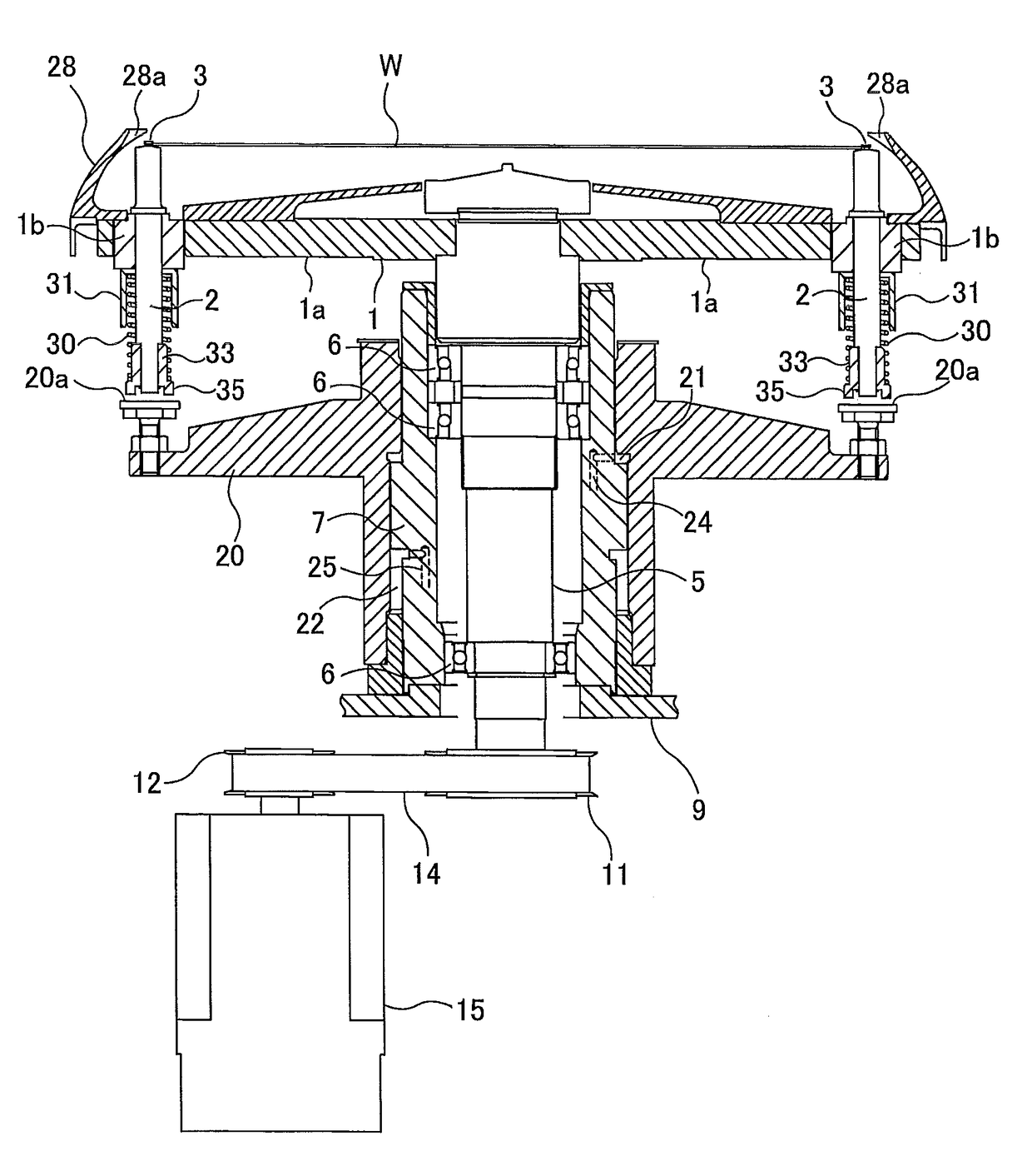
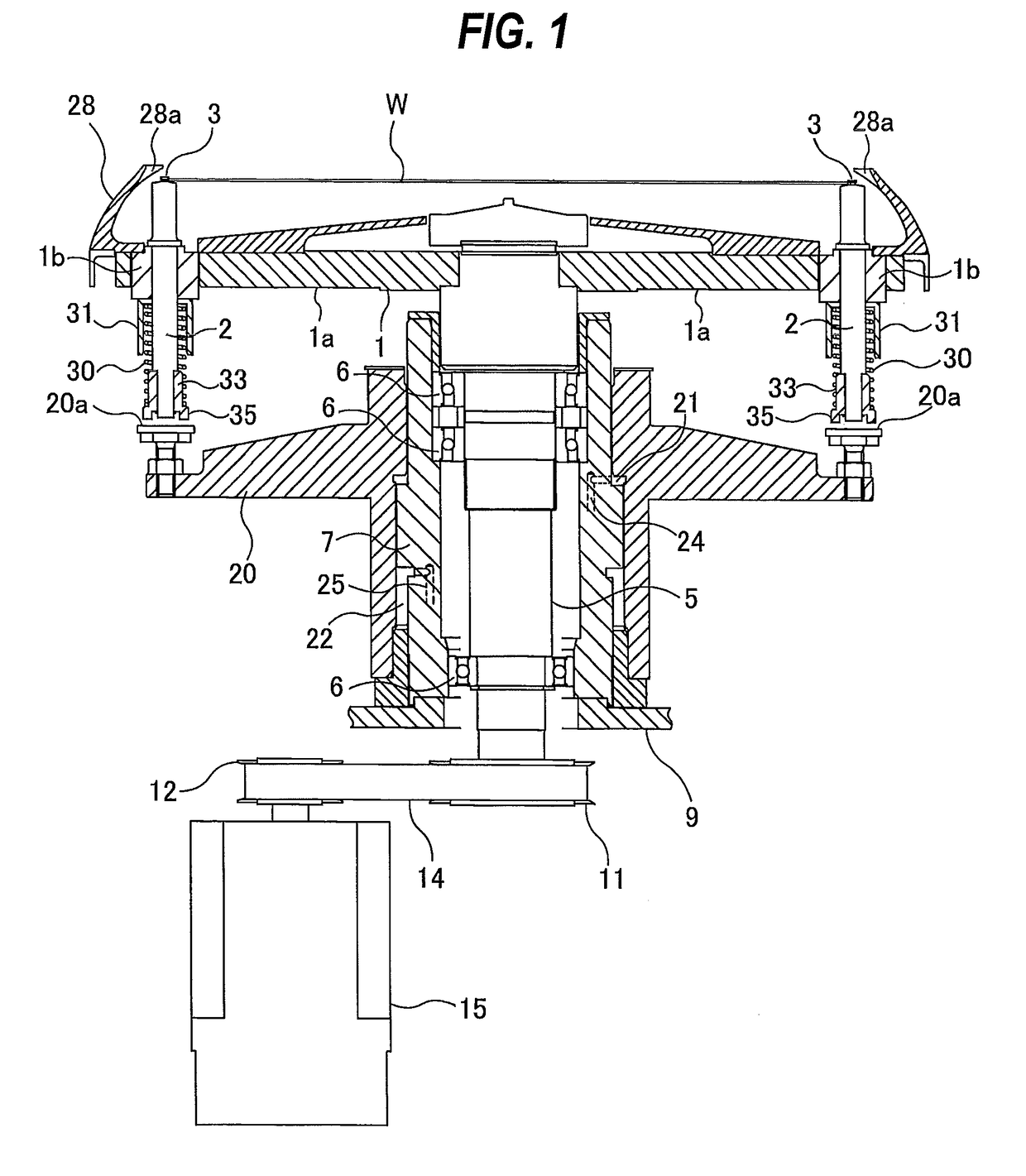
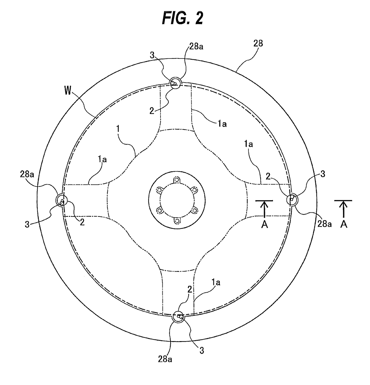
[0036]Embodiments will now be described in detail with reference to the drawings. FIG. 1 is a vertical cross-sectional view of a substrate holding apparatus according to an embodiment. FIG. 2 is a plan view of the substrate holding apparatus shown in FIG. 1.

[0037]As shown in FIG. 1 and FIG. 2, the substrate holding apparatus includes a base 1 having four arms 1a, four support posts 2 supported by distal ends of the arms 1a, respectively, and four chucks 3 provided on upper ends of the support posts 2, respectively. Each of the support posts 2 is movable upwardly and downwardly relative to the base 1, and is rotatable about its own axis. The support posts 2 are provided with the chucks 3 for holding a periphery of a wafer W which is an example of a substrate. The support posts 2 and the chucks 3 are arranged at equal intervals along the periphery of the wafer W.

[0038]The base 1 is secured to an upper end of a rotational shaft 5, which is rotatably supported by bearings 6. The bearing...


PUM


Abstract

There is disclosed an improved substrate holding apparatus which can minimize deformation of a spring, which is provided to bias a support post for supporting a substrate, even when a large centrifugal force acts on the spring. The substrate holding apparatus includes: a support post movable in an axial direction thereof; a chuck provided on the support post and configured to hold a periphery of a substrate; a spring biasing the support post in the axial direction; a first structure configured to restrict a movement of an upper portion of the spring in a direction perpendicular to the axial direction of the support post; and a second structure configured to restrict a movement of a lower portion of the spring in a direction perpendicular to the axial direction of the support post.

Description

CROSS REFERENCE TO RELATED APPLICATION[0001]This document claims priority to Japanese Patent Application Number 2014-231817 filed Nov. 14, 2014, the entire contents of which are hereby incorporated by reference.BACKGROUND[0002]A substrate holding apparatus is known as a device for holding a periphery of a substrate, such as a wafer, and rotating the substrate. Such a substrate holding apparatus is used in a processing apparatus, such as a drying apparatus for drying a substrate by spraying an IPA vapor onto a surface of a substrate while rotating the substrate.[0003]The above-described substrate holding apparatus includes a plurality of support posts for supporting a periphery of a substrate. These support posts are arranged along the periphery of the substrate. A spring is disposed around each of the support posts so that the support posts are biased downwardly by the springs. The support posts are elevated by a lifter. When the substrate is transferred from a transfer robot to the...

Claims


Application Information

Patent Timeline
Patent Type & Authority Patents(United States)
IPC IPC(8): H01L21/687B25B5/00B25B5/14
CPCH01L21/68728H01L21/68721H01L21/6875H01L21/68764H01L21/68785H01L2221/683
Inventor TOYOMURA, NAOKIMIYAZAKI, MITSURUINOUE, TAKUYA
Owner EBARA CORP
Learn More