Filling spout whose flow rate can be adjusted by a single actuator device
a technology of actuator device and filling spout, which is applied in the direction of water supply installation, liquid bottling, liquid dispensing, etc., can solve the problems of preventing the filling cycle from taking place properly, splashing on the outside of the container, and froth formation, so as to minimize the risk of froth formation and minimize the effect of jet deformation
- Summary
- Abstract
- Description
- Claims
- Application Information
AI Technical Summary
Benefits of technology
Problems solved by technology
Method used
Image
Examples
second embodiment
As shown in FIG. 5, the filling spout of the invention comprises a valve body 101 receiving a valve member 102 provided with radial fins 113 over an upstream portion thereof, and a flow-rate adjustment member 103 disposed upstream from the valve member 102. The flow-rate adjustment member 103 is made up of a cylindrical upstream portion 103.1 and of a frustoconical downstream portion 103.2. The flow-rate adjustment member 103 is mounted to slide facing a portion of the valve body 101 that is provided with a constriction 104 of varying section, and it is connected rigidly to a core 111 provided with radial fins 112 and extending axially below the adjustment member 103. The core 111 is slidingly mounted in a tube 129 made of non-magnetic material which is itself tightly mounted to form a portion of the valve body surrounded by an electromagnetic winding 105 secured to the valve body 101. The electromagnetic winding 105 is connected in known manner to electrical power supply control me...
third embodiment
the filling spout operates analogously to the second embodiment of the filling spout.
The plurality of permanent magnets 125 make it possible to increase the magnetic power generated when the electromagnetic winding 105 is energized.
The configuration of the electromagnetic actuator device makes it possible for a given displacement of the slide to reduce the current fed to the electromagnetic winding, and, for the same voltage, to lift a larger mass.
As above, the fins 115 center the valve member 102 and the slide 111, and guide the flow.
The washer 119 makes it possible to maintain the top surface 124 of the slide 111 spaced apart from the ring 118, in order to leave a passageway for the filling substance, thereby guaranteeing that the flow of filling substance is distributed optimally, and that the flow rates are uniform. By moving upwards during operation of the filling spout, the slide 111 causes the washer 119 to be raised with it, the lugs 121 on the washer then coming into contac...
first embodiment
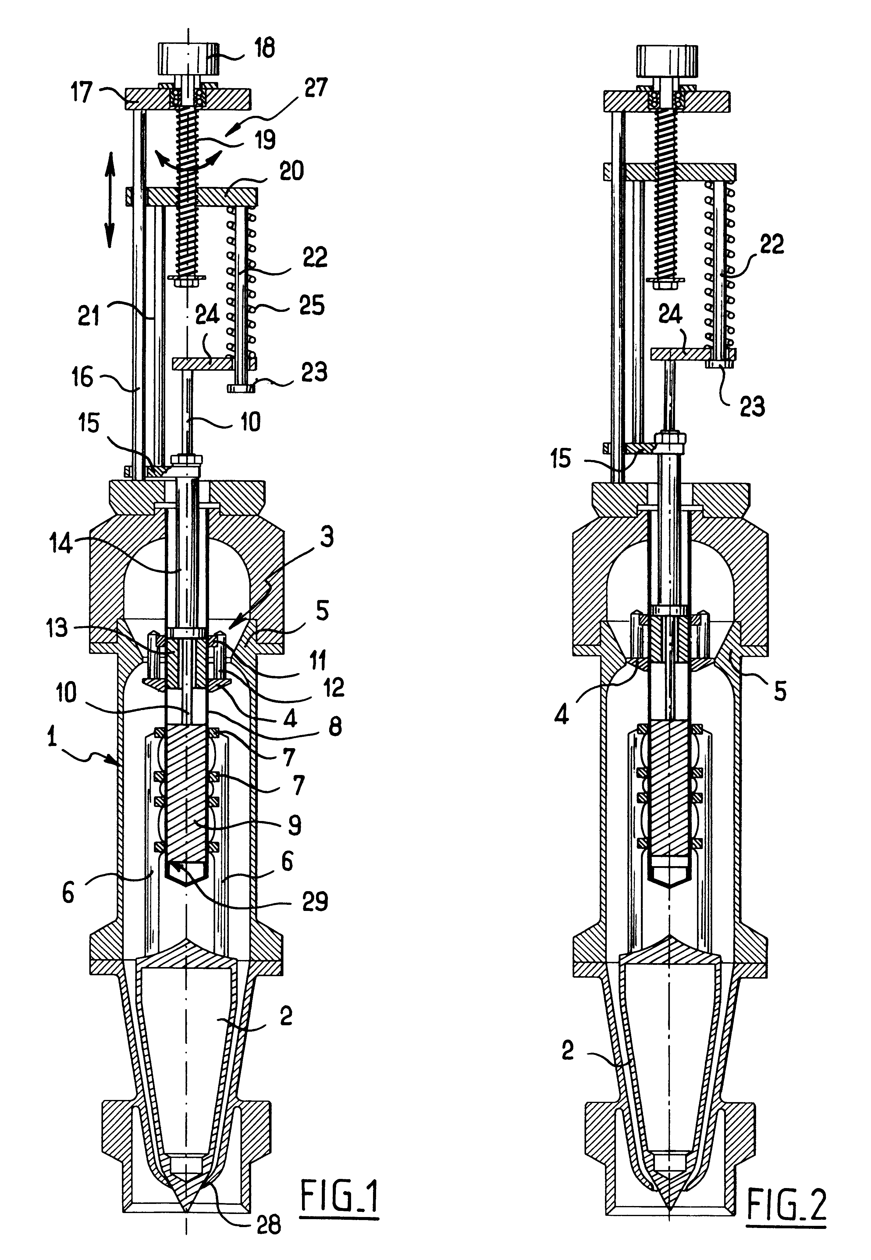
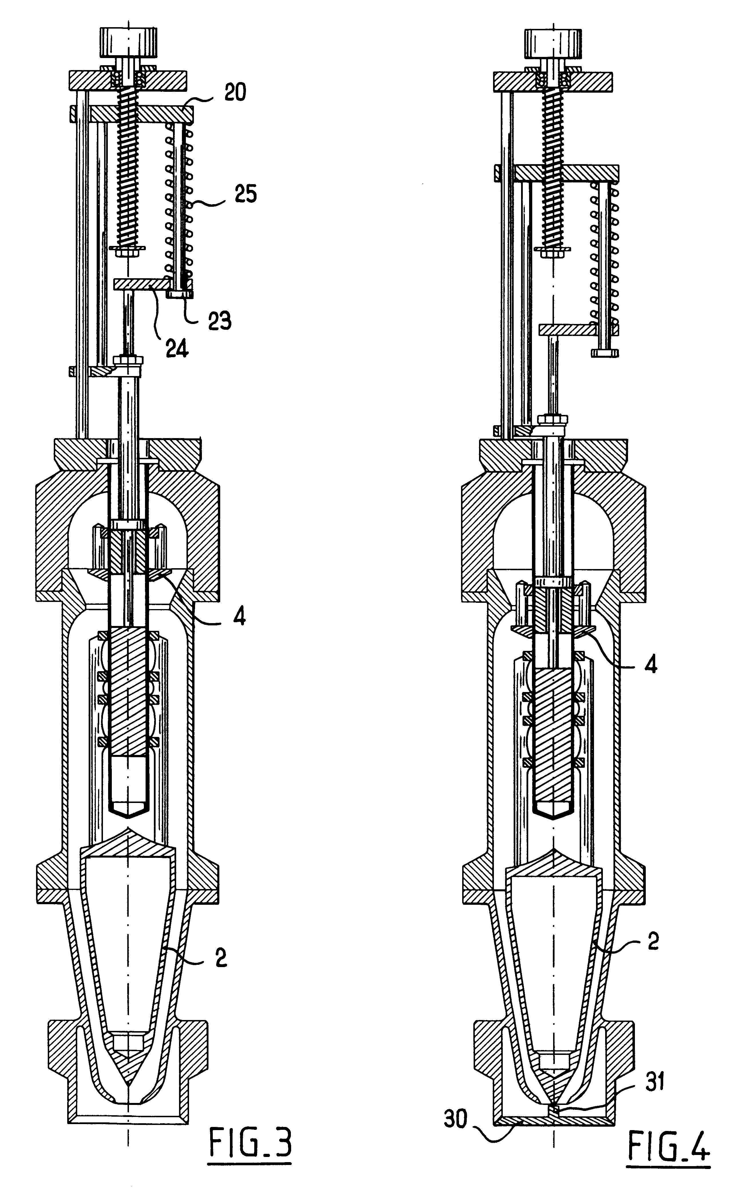
Although, in the first embodiment, the deformable link member is illustrated by a spring disposed around a guide rod, it is possible to replace said spring with an elastomer block disposed between the control member 20 and the valve member control element 24, and fixed to said control member and to said control element.
Similarly, in the first embodiment, although the guide rod 22 is shown separate from the link rod 21, it is possible to mount the control element 24 to slide on said link rod 21, the spring 25 being disposed as above between the actuating member 20 and the valve member control element 24. The end-of-stroke abutment can then be provided either by a collar fixed to the link rod 21 below the valve member control element 24 or by the top end of the control tube 14.
Although the first embodiment is described with reference to a stepper actuating motor, it is also possible to implement the invention by replacing the stepper motor with an actuator or with any other actuating ...
PUM
 Abstract
Description
Claims
Application Information
 - R&D
- Intellectual Property
- Life Sciences
- Materials
- Tech Scout
- Unparalleled Data Quality
- Higher Quality Content
- 60% Fewer Hallucinations
Browse by: Latest US Patents, China's latest patents, Technical Efficacy Thesaurus, Application Domain, Technology Topic, Popular Technical Reports.
© 2025 PatSnap. All rights reserved.Legal|Privacy policy|Modern Slavery Act Transparency Statement|Sitemap|About US| Contact US: help@patsnap.com


