Multilength tubular transporter

a transporter and multi-tube technology, applied in the directions of transportation and packaging, load securing, transportation items, etc., can solve the problems of slow process, inability to use the deck of the ship for anything, and the manual handling process can take quite a long time, so as to improve the payload capacity and facilitate the lifting

Inactive Publication Date: 2006-11-07
PARAGON INDS
View PDF11 Cites 47 Cited by
  • Summary
  • Abstract
  • Description
  • Claims
  • Application Information

AI Technical Summary

Benefits of technology

[0010]Therefore, one object of the present invention is to provide a multilength tubular transporter which enables transport of tubulars having a wide range of lengths and diameters.
[0013]Another object of the present invention is to provide a multilength tubular transporter which allows one-time loading of tubulars throughout the transportation cycle.
[0014]Still another object of the present invention is to provide a multilength tubular transporter which permits easy lifting by forklift or cables.
[0015]Another object of the present invention is to provide a multilength tubular transporter which provides substantially improved payload capacity, including the ability to transport a wide range of equipment and supplies.
[0016]Accordingly, a multilength tubular transporter is provided, comprising a base frame, including at least two main beams, preferably constructed from steel I-beams, wherein the main beams are connected by a plurality of cross members, also preferably constructed from steel I-beams; a floor substantially covering the areas defined by the main beams and cross members; a plurality of substantially vertical guide members connected to each of the main beams; means operatively connected to the base frame for enabling the transporter to be lifted to and from a vehicle; means operatively connected to the base frame for engaging the guide members of a second transporter, wherein the transporters may be securely stacked; and wherein the base frame includes winching means for securing tubulars within the transporter.
[0017]In a preferred embodiment, at least two cross members are constructed in the form of a tube shaped and dimensioned to permit the insertion of a fork of a forklift. Also, the main beams each include a plurality of stacking sockets aligned with and formed to receive guide members of a second transporter, and wherein each of the guide members includes a tapered cap shaped and dimensioned to enable insertion of the guide members into the stacking sockets. Each of the guide members includes a guide channel for receiving divider members between stacks of tubulars. Additionally, the guide members include a plurality of side support pads which are constructed of a material that minimizes deformation to tubulars carried within the transporter. Optionally, the side support pads may be constructed from an elastomeric material, and the floor may comprise a plurality of wooden planks attached to the cross members.

Problems solved by technology

This method of loading and unloading is widely accepted as the way such tasks must be performed, but it is a slow process, particularly when multimodal forms of transportation are required or when the tubulars must be moved several times before reaching their final destination.
Therefore, the deck of the ship is unusable for anything other than tubular transport for the return trip.
It can readily be seen, therefore, that in more complex shipping arrangements, this manual handling process can take quite some time.
This is particularly problematic when participants in the shipping process are not immediately ready to transport the items, and the tubulars must be removed from the previous vehicle and temporarily stored.
The disadvantages of the aforementioned methods are many.
First, as explained in the preceding example, the process of carefully moving small numbers of items is exceedingly slow, especially when each load of tubulars on a vehicle is carried in several stacks.
Second, because of the extensive amount of time required to manually move tubulars from place to place, it can be an unduly expensive operation.
In smaller jobs requiring a relatively small number of items, the expense of moving tubulars is often prohibitively expensive.
Finally, as loading and unloading frequency increases, so does the risk that accidents will happen as tubulars are moved.
However, the Ferguson frames have a number of notable deficiencies.
First, there is no integrated winch and strap assembly for use in securing a loaded frame, ostensibly because it relies upon an upper bar to mechanically lock the tubulars in place.
Second, it does not provide full-length support for longer tubulars, resulting in possible damage to the exposed ends of the tubulars and their threads.
Third, the Ferguson frames are not structurally capable of handling larger payloads in the range of 50,000 pounds.
Fourth, the reliance on a four-point contact as the frames are stacked is less preferable to a more stable and redundant arrangement.
Finally, the Ferguson frames appear to be designed only for the transportation of tubulars, because there is no multi-purpose floor or other supporting surface to permit the transportation of other equipment.

Method used


Image

  • Multilength tubular transporter
  • Multilength tubular transporter
  • Multilength tubular transporter

Examples


Embodiment Construction

[0031]Unless otherwise noted herein, all construction materials are preferably steel, and all attachments between such components are achieved by welding. Such materials and methods are intended to impart a maximum level of strength and structural rigidity, while keeping the transporter as lightweight and easy to maneuver as possible. Certain features which are used in assembling or operating the invention, but which are known to those of ordinary skill in the art and not bearing upon points of novelty, such as screws, bolts, nuts, welds, and other common fasteners, may not be shown for clarity.

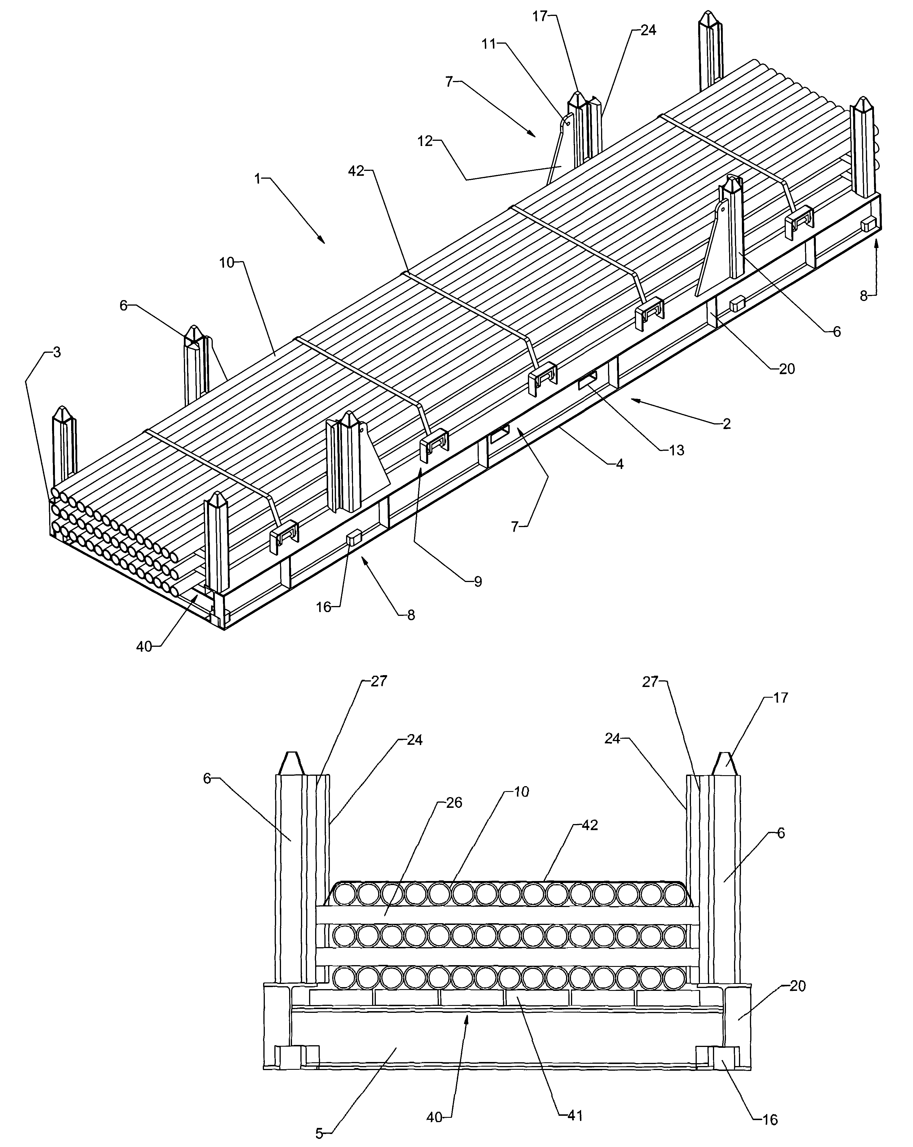
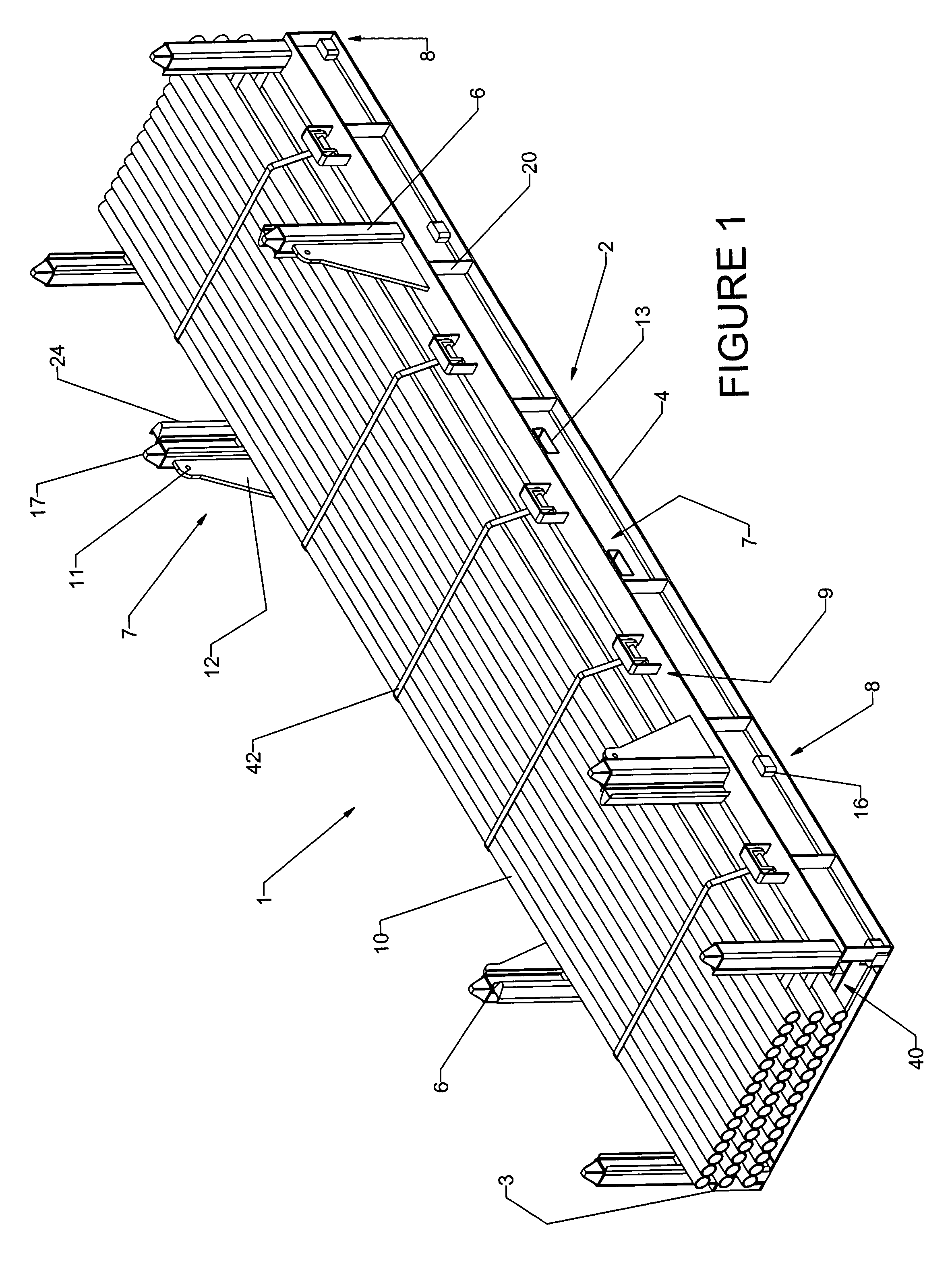
[0032]Turning now to the figures, a multilength tubular transporter 1 is illustrated in FIG. 1 in a loaded condition as being generally comprised of a base frame 2, including at least two main beams 3,4 which are connected by a plurality of cross members 5. Each cross member 5 is preferably constructed from steel I-beams, such as a W12×45 wide flange I-beam, to achieve the desired structural ...


PUM


Abstract

A multilength tubular transporter is provided, comprising a base frame, including at least two main beams, wherein the main beams are connected by a plurality of cross members, a floor substantially covering the areas defined by the main beams and cross members; a plurality of substantially vertical guide members connected to each of the main beams; a lifting arrangement operatively connected to the base frame for enabling the transporter to be lifted to and from a vehicle; a stacking device operatively connected to the base frame for engaging the guide members of a second transporter, wherein the transporters may be securely stacked; and wherein the base frame includes one or more winches for securing tubulars within the transporter.

Description

BACKGROUND OF THE INVENTION[0001]I. Field of the Invention[0002]The present invention relates generally to the loading, transportation, and unloading of pipe and tubing, and more particularly to devices used to transport such pipe and tubing.[0003]II. Background and Prior Art[0004]In the oilfield industry and many other industries, a wide variety of pipes and tubes (hereinafter “tubulars”) are used. Tubulars are often loaded directly onto flatbed trailers and stacked with divider boards in between the layers, and they are typically retained on the trailer by a series of vertical posts inserted into the outer edge of the trailer. When the tubulars are loaded or unloaded, they are moved only a few items at a time by forklift or crane, each time having to raise the tubulars above the side posts to clear the trailer. If the tubulars are being unloaded for use at their final destination, they are usually moved onto nearby pipe racks and stacked in similar fashion. This method of loading ...

Claims


Application Information

Patent Timeline
Patent Type & Authority Patents(United States)
IPC IPC(8): B60P7/08B60P7/12B65D88/02B65D88/12B65D90/00
CPCB60P7/12B65D88/022B65D88/129B65D90/006B65D2590/005B65D2590/0058
Inventor GUARISCO, SR., LEONARD J.GUARISCO, JR., LEONARD J.GUARISCO, PATRICK D.
Owner PARAGON INDS
Why Eureka
Try Eureka