Method and compression apparatus for introducing residual compression into a component having a regular or an irregular shaped surface

a compression apparatus and component technology, applied in the direction of grinding/polishing apparatus, grinding machines, manufacturing tools, etc., can solve the problems of failure of metallic machines and various structural components, failures generally initiated from the surface of the component, and uncontrolled manual process

Active Publication Date: 2014-01-09
SURFACE TECH HLDG
View PDF3 Cites 44 Cited by
  • Summary
  • Abstract
  • Description
  • Claims
  • Application Information

AI Technical Summary

Benefits of technology

[0016]In another preferred embodiment of the invention, the flexible arm assembly operates to provide one degree of freedom in flexure such that th

Problems solved by technology

Many metallic machines and various structural components are subject to failure by fatigue, corrosion fatigue, or stress corrosion cracking (SCC).
Failures generally initiate from the surface of the component in highly stressed areas, often from scratches, corrosion pits, or other surface damage that creates a shallow notch or indentation that produces a local stress concentration.
Hammer peening of welds is an ancient practice known to eliminate residual tension caused by shrinkage of the hot weld, but is an uncontrolled manual process.
However, all such methods have limitations that make automated application to certain surfaces, such as irregular topography surfaces often found in welded assemblies, difficult or undesirable.
Automated processing of welds or other irregular topography surfaces using CNC control is difficult because the workpiece shapes, surface geometries, or irregularities vary making the process non repeatable.
Therefore, components having irregular topography surfaces, such as manually welded assemblies, cannot be reliably treated because the irregularities may cause the processing tool to be positioned too close or distant from the surface to be effec

Method used


Image

  • Method and compression apparatus for introducing residual compression into a component having a regular or an irregular shaped surface
  • Method and compression apparatus for introducing residual compression into a component having a regular or an irregular shaped surface
  • Method and compression apparatus for introducing residual compression into a component having a regular or an irregular shaped surface

Examples


Embodiment Construction

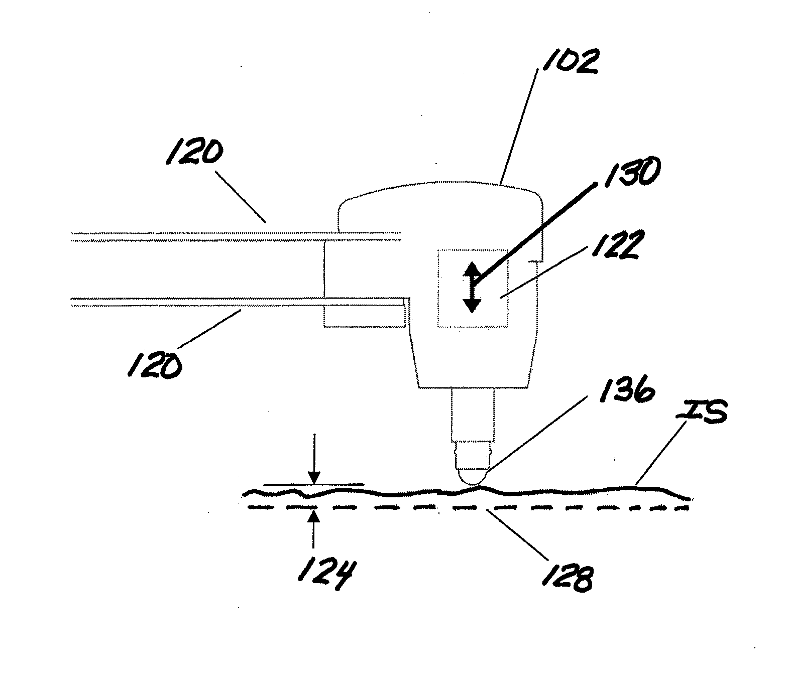
[0073]The present invention relates to inducing compression and cold work along and in the surface of component workpieces. In describing the preferred embodiments of the invention illustrated in the drawings, specific terminology will be resorted to for the sake of clarity. However, the invention is not intended to be limited to the specific terms so selected, and it is to be understood that each specific term includes all technical equivalents that operate in a similar manner to accomplish a similar purpose.

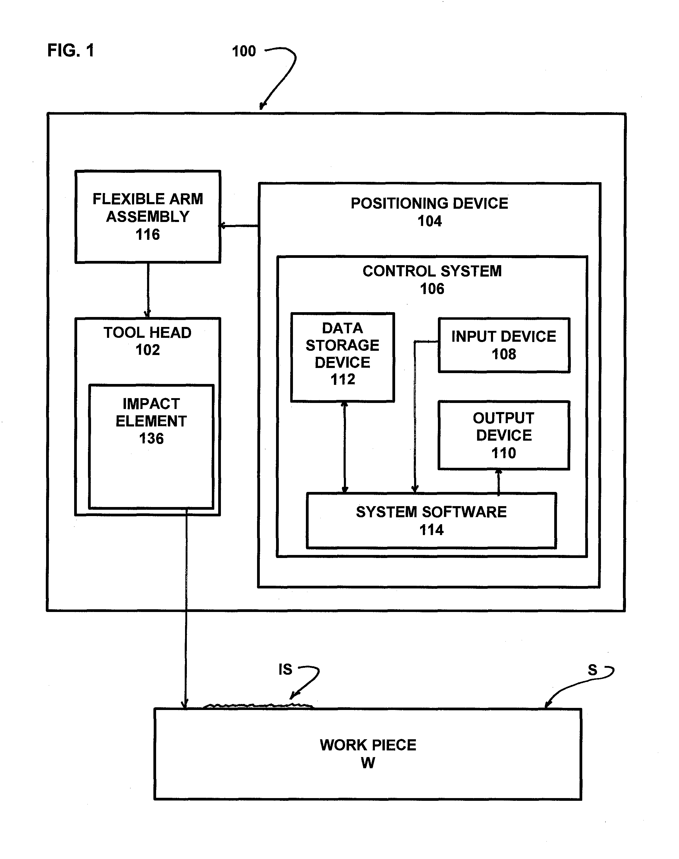
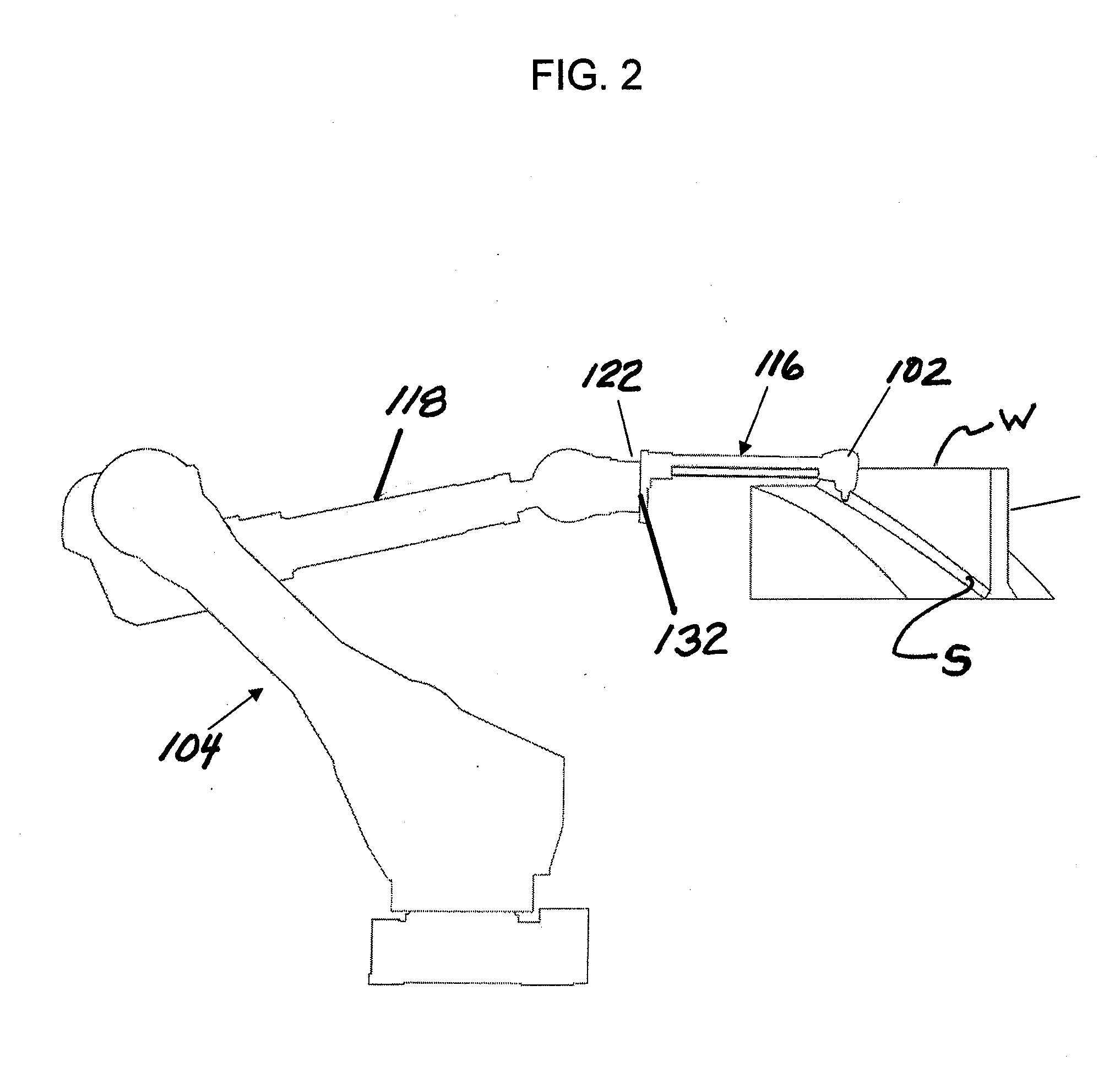
[0074]The apparatus and method of the invention operate to provide controlled plastic strain by compression to create cold work and compressive residual stress along and in the surface of a workpiece having an irregular surface topography, such as welds, castings or re-worked components, for which automated processing, such as be use of CNC controlled machines or robots was not previously practical or reliable. In a preferred embodiment of the invention, the compression apparat...


PUM

PropertyMeasurementUnit
Angleaaaaaaaaaa
Forceaaaaaaaaaa
Structureaaaaaaaaaa

Abstract

A method and apparatus for improving the fatigue and stress corrosion cracking performance of irregular surfaces, such as welds assemblies of components, using a positioning system, such as a robotic or CNC machine, to position a tool head for inducing compression along and into the surface of a workpiece to automatically follow the surface irregularities. The method and apparatus operates to follow a virtual control surface located below the actual surface of the workpiece thereby allowing the irregular topography surface to be uniformly processed with closed loop process control.

Description

CROSS REFERENCE TO RELATED APPLICATION[0001]This application relates to and claims benefit of U.S. provisional patent application No. 61 / 668,111, filed Jul. 5, 2012, entitled: Method and Apparatus for Introducing Residual Compression Into a Component Having an Irregular Shaped Surface and which is incorporated in its entirety by reference.BACKGROUND OF THE INVENTION[0002]This invention relates to inducing compression along and into the surface of a component and more particularly to a method and apparatus for inducing compressive residual stress along and into the surface of a workpiece having a regular or an irregular surface topography.[0003]Many metallic machines and various structural components are subject to failure by fatigue, corrosion fatigue, or stress corrosion cracking (SCC). Failures generally initiate from the surface of the component in highly stressed areas, often from scratches, corrosion pits, or other surface damage that creates a shallow notch or indentation that...

Claims


Application Information

Patent Timeline
IPC IPC(8): B24B39/00
CPCB24B39/006B23P9/04B24B27/0038C21D1/02C21D1/06C21D7/04Y10T29/47
Inventor HAAS, JOHN E.UNGER, LARRY J.LASCELLES, RUSSELL A.PREVEY, MICHAEL P.PREVEY, III, PAUL S.
Owner SURFACE TECH HLDG
Why Eureka
Try Eureka