
Fastener element for connecting a structural part to a support part

Inactive Publication Date: 2007-02-20
ITW AUTOMOTIVE PRODS
View PDF10 Cites 27 Cited by
  • Summary
  • Abstract
  • Description
  • Claims
  • Application Information

AI Technical Summary

Benefits of technology

[0009]It is the object of the invention to provide a fastener element for connecting a structural part, in particular a lining, to a support part, in particular a body sheet of an automobile, which can be manufactured with little effort and does not cause either corrosion problems or noise.
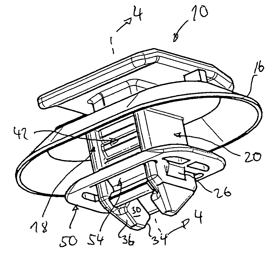
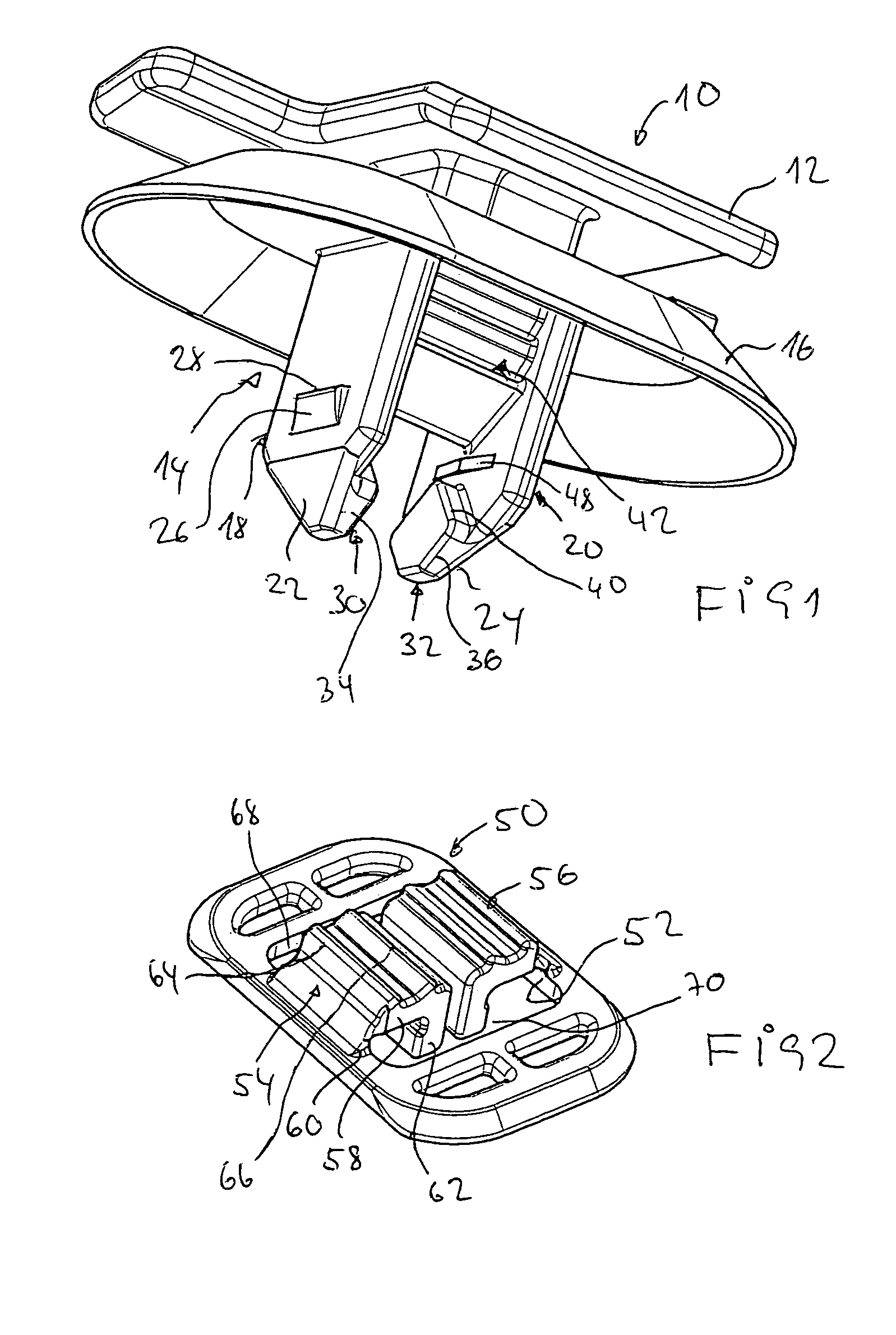
[0011]The washer-like locking part, which can be of an approximately rectangular shape and has a measure which is larger than the diameter of the fasting hole in any case, has an approximately rectangular aperture or opening. Two opposed sides of the aperture have pivotically formed thereto holding portions each which are approximately L-shaped in the cross-section. Each holding portion has a first web portion formed to the locking part and a second web portion which extends from the upper side of the locking portion to the lower side of the locking portion through the aperture. The dimensions of the aperture and holding portions are such that a slot is formed each between the respective other opposed sides of the aperture and the two holding portions, into which an outer web can be fittingly inserted from the upper side of the locking part in such a way that the lower ramp surfaces of the projections pivot the holding portions away from each other and the lower sides of the second web portions can come to lie on the upper ramp surfaces. In this assembly step, the outer webs are introduced into the slots of the locking part by a certain amount. This helps obtain a pre-assembly position of the parts relative to each other. Shoulders on the outsides of the outer webs can grip under the washer-like locking part at the lower side and secure the locking part against removal from the outer webs of the fastener body.
[0013]The lower end of the transverse web is approximately triangular in cross-section parallel to the outer webs to make it easier to pivot the holding portions as described. There is a spacing which facilitates the engagement of the transverse web between the holding portion in a stress-relieved state. Moreover, a rounded portion may be provided at the outer transition from the first web portion to the second one.
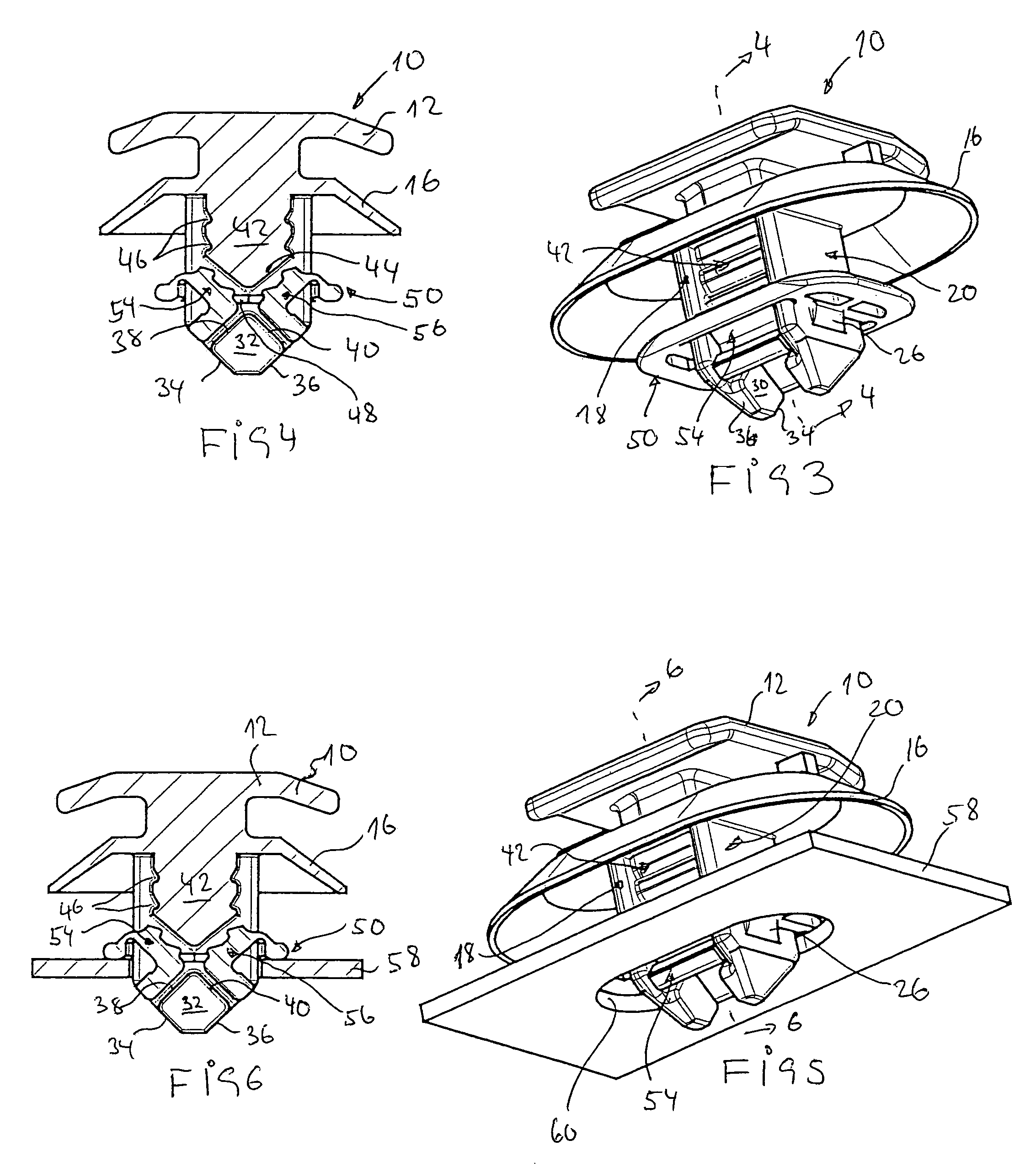
[0014]To achieve a sufficient holding force of the inventive fastener element in the fastening hole, another aspect of the invention provides that the surfaces facing each other of the first web portions of the holding portions include at least one locking portion the outside of the transverse web facing them is provided with at least a second locking portion cooperating with the first locking portion. It is preferred to provide two locking teeth or locking gaps spaced in an axial direction where different sheet thicknesses of the support part may be employed. The locking teeth or locking grooves are such as to allow the transverse web to be introduced relatively easily in between the opposed holding portions whereas relatively large holding forces are produced in the opposite direction. However, if sufficient pulling force is applied it is possible to overcome the locked state, which causes the holding elements to fold back to their initial state and to remain there in a position as existed after the pre-assembly. The inventive fastener element can now be used anew.
[0015]The inventive fastener element has a number of advantages. There is no wear during the assembly and disassembly. Assembly and disassembly forces are substantially constant. The inventive fastener element allows to precisely harmonize the holding and assembly forces. It is ready possible to mount it in fastening holes even if burr left from punching has remained therein. Furthermore, a relative large tolerance is possible with regard to the size of the fastening hole and the thickness of the support part. The inventive fastener element can be manufactured in a low-expenditure injection molding process. Its use for different hole shapes is also possible.

Problems solved by technology

This causes the holding forces to weaken and the fastener element to fail, in an extreme case, when the number of assembly cycles increases.

Method used


Image

  • Fastener element for connecting a structural part to a support part
  • Fastener element for connecting a structural part to a support part
  • Fastener element for connecting a structural part to a support part

Examples


Embodiment Construction

[0027]The fastener body 10 shown in FIG. 1 has an elongate head 12 and a shank generally designated 14 which is connected to the head 12 and has two parallel spaced outer webs 18, 20 below an oval, conical sealing flange 16. The outer webs 18, 20 are elongated rectangular in cross-section with the longer sides of the outer webs 18, 20 extending parallel to each other. The outer webs 18, 20 have tapering introduction portions 22, 24 at the free end. On the outer surfaces facing away from each other, the outer webs 18, 20 have elevations one of which is shown at 26. The elevations define a shoulder 26 facing the head 12, reference to which will be made farther below. The outer webs have projections 30, 32 on the inner surfaces facing each other. As can be appreciated from FIG. 4, for example, in which the fastener body 10 is shown in section the projections 30, 32 have lower ramp surfaces 34, 36 which converge downwardly towards the free end of the outer webs 18, 20 and upper ramp sur...


PUM


Abstract

A fastener element includes a fastener body and a locking part. The body includes a shank having two outer webs interconnected by a transverse web. The outer webs have projections including upper and lower ramp surfaces. The locking part includes an aperture having first and second pairs of opposing edges, and L-shaped holding portions each having a first web portion linked to one of the first opposing edges, and a second web portion extending into the aperture. When the outer webs are introduced into slots between the second opposing edges and the holding portions, the lower ramp surfaces move the holding portions away from each other and the second web portions engage the upper ramp surfaces from above. If the shank is introduced in a fastening hole of a support part while the locking part engages the support part, the holding portions are further pivoted away from each other and the second web portions grip the edge of the fastening hole.

Description

RELATED APPLICATIONS[0001]The present application is based on, and claims priority from, German Application Number 103 49 449.9, filed Oct. 23, 2003, the disclosure of which is hereby incorporated by reference herein in its entirety.[0002]1. Field of the Invention[0003]The invention relates to a fastener element for connecting a structural part, in particular a lining, to a support part having a fastening hole, in particular a body sheet of an automobile.[0004]2. Background of the Invention[0005]A multiplicity of so-called chips or fastener elements have become known for the fastening of linings and other attachments to the automobile body. The fastener elements, which normally are manufactured from a plastic, have a head for connection to the part to be fastened and a base or shank which is forced into or lockingly inserted into an aperture of the body. The aperture or hole in the body may be of various shapes, e.g. that of a rectangle, elongated hole, circular hole or molded hole....

Claims


Application Information

Patent Timeline
IPC IPC(8): E04F19/02A44B21/00F16B13/04A44B99/00B60R13/02F16B5/06F16B21/08
CPCB60R13/0206F16B21/08Y10T24/309F16B5/065
Inventor KUHNLE, UWEFERDINAND, MARKUS
Owner ITW AUTOMOTIVE PRODS
Learn More