
Pressure relief valve

a pressure relief valve and valve body technology, applied in the field of pressure relief valves, can solve the problems of affecting the appearance of the product, affecting the operation of the film, affecting the product appearance, etc., and achieve the effect of preventing excessive pressure from building within the container and distorting the appearan

Inactive Publication Date: 2007-02-20
PULTEK L L C
View PDF8 Cites 90 Cited by
  • Summary
  • Abstract
  • Description
  • Claims
  • Application Information

AI Technical Summary

Benefits of technology

[0003]Pressure relief valves are often used to vent product packaging which contains materials which may produce gasses. In flexible wall packaging or containers, a build-up of gasses within the container often distorts the appearance of the product or damages the packaging, among other things. To prevent excessive pressure from building within the container, a pressure relief valve is used to vent the gasses while also sealing the contents from the environment through the use of a flexible film or membrane.
[0004]However, in use, and especially when numerous cartons are packaged together in bulk, the operation of the film is often obstructed or impeded by an adjoining carton which is placed in contact with the membrane or film. To solve this problem, outer rails are often used which prevent an object from physically contacting the flexible film. This, of course, leads to use of additional materials, manufacturing steps, and ultimately, increased costs.
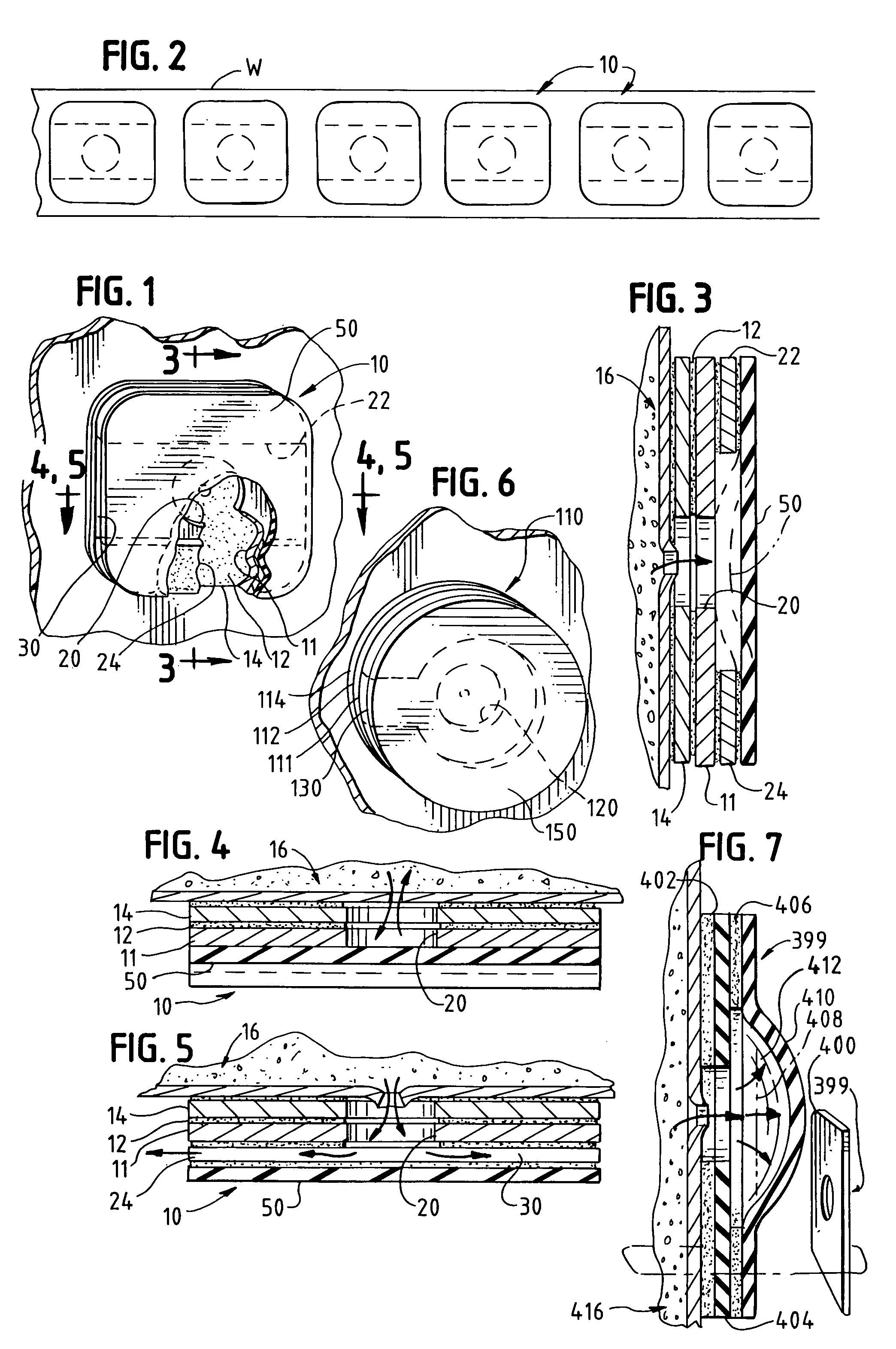
[0005]The present invention eliminates the use of outer rails through the use of at least one inner rail that defines a passageway which is recessed from an aperture located on the valve. In a closed position, the film covers the aperture, and in an open position, the film is raised above the aperture to permit the aperture to be in communication with the passageway in order to vent the container.

Problems solved by technology

In flexible wall packaging or containers, a build-up of gasses within the container often distorts the appearance of the product or damages the packaging, among other things.
However, in use, and especially when numerous cartons are packaged together in bulk, the operation of the film is often obstructed or impeded by an adjoining carton which is placed in contact with the membrane or film.
This, of course, leads to use of additional materials, manufacturing steps, and ultimately, increased costs.

Method used


Image

  • Pressure relief valve
  • Pressure relief valve

Examples


Embodiment Construction

[0014]Set forth below is a description of what are currently believed to be the preferred embodiments or best examples of the invention claimed. Future and present alternatives and modifications to the preferred embodiments are contemplated. Any alternates or modifications having insubstantial changes in function, in purpose, in structure or in result are intended to be covered by the claims of this patent.

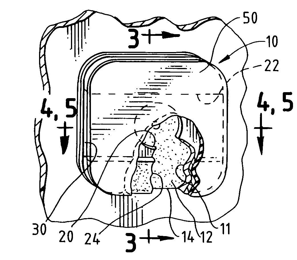
[0015]As shown in FIG. 1, one embodiment of the present invention includes a pressure relief valve 10 having a base 11 which may include an adhesive layer 12 and a release liner 14. The adhesive layer 12 allows the base to be mounted to a package or support surface 16.

[0016]An aperture 20 is included on base 11 which is often located over an opening on package 16. Base 11 may be made of a number of materials known to those of skill in the art including Polyethylene Terephthalate by DuPont Teijin Films.

[0017]As is also shown in FIGS. 1–5, inner rails 22 and 24 are provided on base ...


PUM


Abstract

A pressure relief valve that is mountable to protect packaging so as to vent pressurized gases contained within the packaging. The present invention also pertains to a pressure relief valve which includes at least one passageway defined by at least one inner rail and which is in communication with an aperture.

Description

[0001]This application is a continuation-in-part of application Ser. No.: 09 / 705,524, filed Nov. 3, 2000, now abandoned.BACKGROUND OF THE INVENTION[0002]The present invention relates to a pressure relief valve that is mountable to product packaging so as to vent pressurized gasses contained within the packaging. More specifically, the present invention is a pressure relief valve which includes at least one passageway defined by at least one inner rail and which is in communication with an aperture.SUMMARY OF THE INVENTION[0003]Pressure relief valves are often used to vent product packaging which contains materials which may produce gasses. In flexible wall packaging or containers, a build-up of gasses within the container often distorts the appearance of the product or damages the packaging, among other things. To prevent excessive pressure from building within the container, a pressure relief valve is used to vent the gasses while also sealing the contents from the environment thro...

Claims


Application Information

Patent Timeline
IPC IPC(8): F16K15/14B65D33/01B65D77/22F16K17/164
CPCB65D77/225Y10T137/7879Y10T137/7888F16K15/144
Inventor ENGEL, ROGER K.CARROLL, DAVE
Owner PULTEK L L C
Learn More