
Method and device related to a retrievable well plug

Active Publication Date: 2007-02-20
INTERWELL NORWAY AS
View PDF12 Cites 48 Cited by
  • Summary
  • Abstract
  • Description
  • Claims
  • Application Information

AI Technical Summary

Benefits of technology

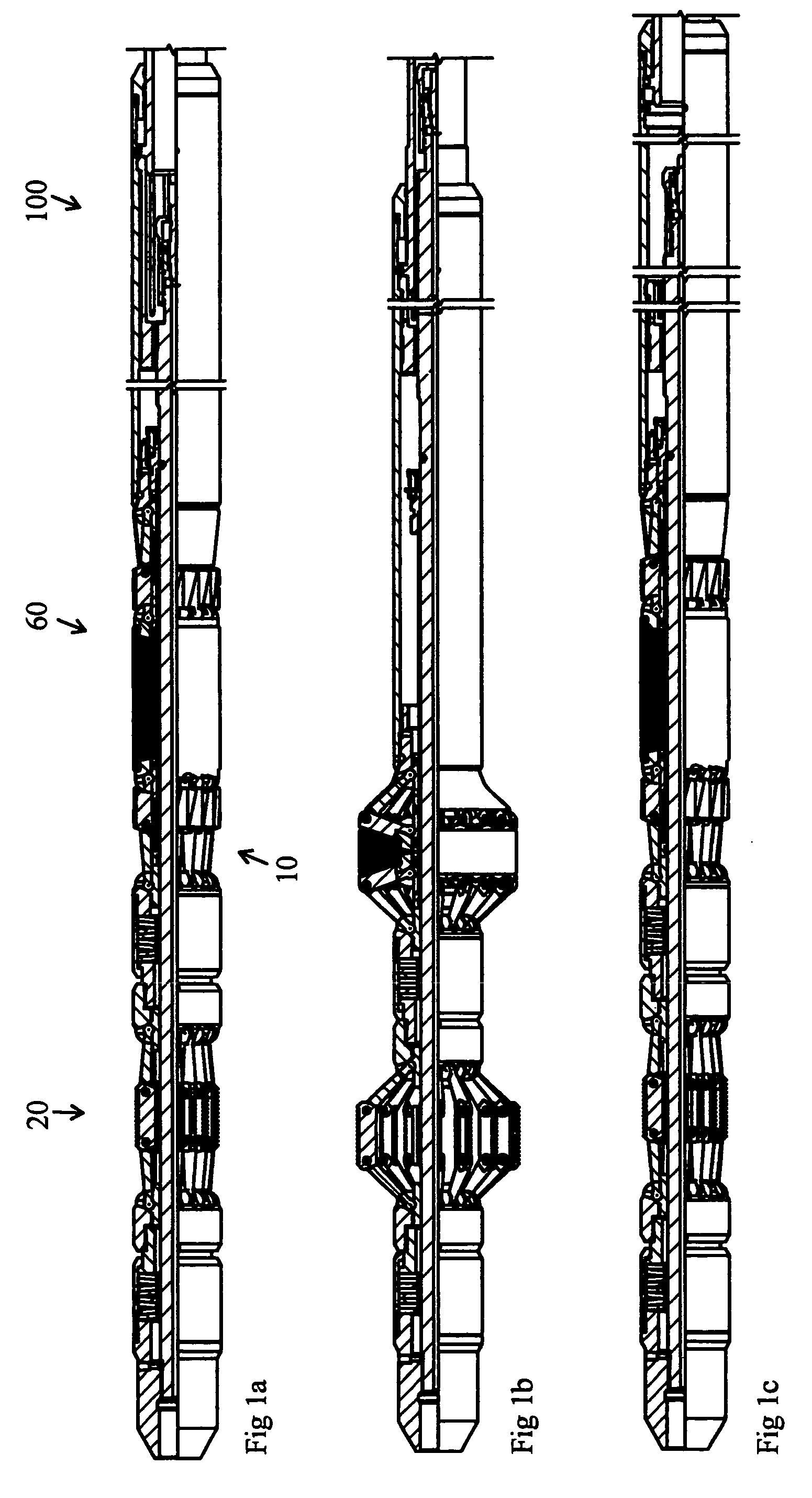
[0012]An object of the present invention is to provide a setting method such that sufficient anchoring of the well plug towards the pipe wall is maintained before the start of the packer element expansion, so that the well plug can be set in a well with liquid and or gas flow.
[0013]A further object of the present invention is to provide a retrieval method whereby the anchoring of the well plug towards the pipe wall is maintained until the packer element is in a contracted state, so that the well plug can be retrieved from a well with liquid and / or gas flow.
[0014]A further object of the present invention is to provide a retrievable well plug which avoids the abovementioned disadvantages. An object is to provide a physically tight mechanical barrier on each side of one packer element, thereby forming the two mechanical barriers in expanded position constituting radial walls which prevent extrusion of the packer element under strain of pressure.

Problems solved by technology

Such a fastening device will place restrictions on the number of linking-pairs to be used, and consequently also place restrictions on the sealing quality of the mechanical barrier.
This can cause problems when the well plug is to be retrieved.
A possible disruption of one of the two symmetrical packer elements can result in a removal of mechanical connection between the upper part of the well plug and the expanding anchoring device.
Consequently loosening of the anchoring device at the time of retrieval of the well plug becomes difficult.
The described anchoring device provides a limitation of the expansion of the well plug, and requires a long setting wandering (setting movement) to achieve sufficient anchoring force towards the pipe wall.

Method used


Image

  • Method and device related to a retrievable well plug
  • Method and device related to a retrievable well plug
  • Method and device related to a retrievable well plug

Examples


first embodiment

[0048]the link connections 62, 64 will now be described with reference to FIGS. 7a and 7b. In the following, this embodiment will be referred to as an unsymmetrical link connections. There it is shown a link 76 of a link pair making up the link connection 62, 64. The link 76 is meant to support the packer element 66 and the structure of the link is essential. A second link 77 of the link pair making up the link connection 62, 64 can be a corresponding link, but preferably has a simpler structure (shown in FIG. 10) since this link will not be in touch with the packer element 66. The link 77 will be described below. The link 76 has a generally T-shaped cross section, and comprises an arm 78 with an end 80 formed as a ball. The other end of the arm 78 has an opening 82 for pivotable fastening with a bolt or similar to the other link 77 (FIG. 10) making up the link connection 62, 64. Further, the link 76 has an upper supporting surface 84, an upper supporting surface 86, a lower support...

second embodiment

[0050]the link connection 62, 64 will now be described with reference to FIGS. 8a and 8b. In this embodiment, the mechanical barrier comprises links of two types, an outer link 174 (FIGS. 8a and 12) and an inner link 176 (FIGS. 8b and 13). Both types of links have a generally T-shaped cross section, and in this embodiment will the following be referred to as symmetrical links.

[0051]Similar to the embodiment described above, the outer link 174 and the inner link 176 has an arm 178 with a ball-shaped end 180. In the opposite end, the arm 178 comprises an opening 182 for pivotable fastening by means of a bolt or similar to the other link 77 (FIG. 10) of the link pair making up the link connection 62, 64. This embodiment will in the following be referred to as symmetrical links.

[0052]The outer link 174 comprises a preferably curved upper supporting surface 184, where the arm 178 is disposed generally centrally below the supporting surface 184. Further, the outer link 174 comprises lower...


PUM


Abstract

A retrievable well plug has a through shaft (12) with link connections (62, 64) and a packer element (66). By pushing the link connections (62, 64) and the packer element towards each other, the link connections (62, 64) and the packer element (66) expand radially, such that a mechanical barrier for the packer element (66) is formed. The links (76; 174, 176) have a generally T-shaped cross sectional profile and include an arm (78) with an end (80) meant for fastening to the fastening devices (72, 74). The other end of the arm (78) fastens to the second link (77) of the link connection (62, 64). Upper supporting surfaces (84, 86; 184; 192, 194) of the links (76; 174, 176) form an approximately tight mechanical barrier against the packer element (66) in an expanded position. The anchoring device (20) has a number of gripping devices (22), wherein the gripping devices (22) at setting of the well plug (10) expand radially, thereby providing an anchoring of the well plug (10) to the well bore wall.

Description

CROSS-REFERENCE TO RELATED APPLICATION[0001]This application claims the benefit of Norwegian Patent Application No. 20031489, filed on Apr. 5, 2003, which hereby is incorporated by reference in its entirety.BACKGROUND OF THE INVENTION[0002]1. Technical Field of the Invention[0003]The present invention relates to a method for use of a retrievable well plug according to claim 1. Further, the invention relates to a retrievable well plug device according to the introduction of claim 4. Further, the invention relates to a well plug anchoring device to keep the well plug in position under pressure according to claim 17.[0004]2. Background of the Invention[0005]Well plugs are used, for example, for zone isolation of oil and gas wells. Such well plugs often have an expandable packer element made of elastic rubber, which seals the well bore for fluid and pressure, and an expandable anchoring device, which is used to hold the well plug in position under pressure. Often, the well plug must pas...

Claims


Application Information

Patent Timeline
IPC IPC(8): E21B23/00E21B23/02E21B33/12E21B33/128E21B33/129
CPCE21B33/1216E21B33/1293E21B33/128E21B23/06
Inventor HIORTH, ESPENANDERSEN, FRODEGUNNARSHAUG, THOMAS
Owner INTERWELL NORWAY AS
Learn More