Lumen woven support

a technology of woven support and lumen, which is applied in the field of medical instruments, can solve the problems of increasing the reaction of the organ to external foreign, increasing the inability of the support to be applied in the practical application of implantation, so as to reduce the risk of restenosis, facilitate implantation, and facilitate implantation.

Active Publication Date: 2020-08-18
LIFETECH SCI (SHENZHEN) CO LTD
View PDF10 Cites 0 Cited by
  • Summary
  • Abstract
  • Description
  • Claims
  • Application Information

AI Technical Summary

Benefits of technology

[0017]In the above-mentioned endoluminal braided stent graft, since the mesh density of the first portion is smaller than that of the second portion, a radial supporting force of the first portion is reduced, and stimulation to a normal lumen wall caused by the first portion is reduced, thereby lowering the risk of restenosis. In addition, the first portion has a good flexibility, the second portion with a greater radial supporting force can provide sufficient anchoring, and therefore, the above-mentioned endoluminal braided stent graft is applicable to practical clinical implantation.

Problems solved by technology

In order to guarantee effective expansion of a diseased lumen, the support is required to have a greater radial supporting force so as to provide sufficient anchoring, but the greater radial supporting force may generate greater stimulation to a normal lumen; for example, the open end portion of the support would generate greater stimulation on the normal lumen, and the greater stimulation would increase organ reaction of an organ to external foreign matters and increase a risk of restenosis.
In conclusion, the support having a uniform integrated woven structure cannot be applicable to practical implantation.

Method used


Image

  • Lumen woven support
  • Lumen woven support
  • Lumen woven support

Examples


Embodiment Construction

[0025]For the purpose of making objects, technical schemes and advantages of the present application more clear, detailed description will be further made to the present application in conjunction with corresponding drawings and embodiments. Obviously, the described specific embodiments are merely an explanation of the present application, but do not limit the present application.

[0026]Unless otherwise defined, all technical and scientific terms used in the text have the same meanings of general understandings of a person skilled in the art of the present application. Terms used in the specification of the present application in the text are intended to describe the specific embodiments, but not to limit the present application. The term “and / or” used in the text includes any and all combinations consisting of one or multiple relevant listed items.

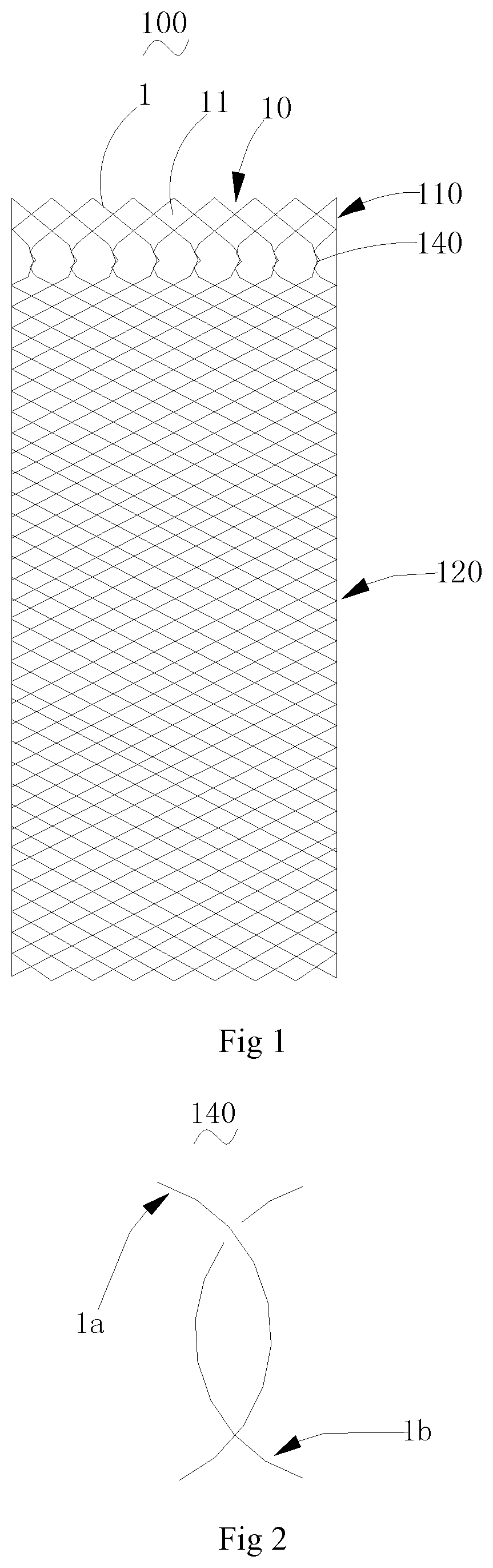
[0027]With reference to FIG. 1, an endoluminal braided stent graft 100 provided by one embodiment of the present application includes a m...


PUM


Abstract

A lumen woven support (100), comprising a netted tube body (10) woven by weaving filaments (1), wherein the netted tube body (10) comprises a first portion (110) and a second portion (120) along an axial direction; the netted tube body (10) further comprises a plurality of first hooked and wound knots (140), at least two weaving filaments (1) from one end of the second portion (120) are hooked and wound to each other in the axial direction of the netted tube body (10) to form a first hooked and wound knot (140) and are then separated, and all the weaving filaments (1) constituting the first hooked and wound knots (140) are woven to form the first portion (110); and the mesh density of the first portion (110) is smaller than that of the second portion (120). In the above-mentioned lumen woven support (100), since the mesh density of the first portion (110) is smaller than that of the second portion (120), the radial supporting force of the first portion (110) is reduced, and the stimulation to a normal lumen wall caused by the first portion (110) is reduced, thereby lowering a risk of restenosis. In addition, the first portion (110) has a good flexibility, the second portion (120) has a greater radial supporting force so as to provide sufficient anchoring, and therefore, the above-mentioned lumen woven support (100) is applicable to practical implantation.

Description

TECHNICAL FIELD[0001]The present application relates to the technical field of medical instruments, and more particularly relates to an endoluminal braided stent graft.BACKGROUND ART[0002]An endoluminal braided stent graft has a radial compression state and a radial expansion state when used. During use, the endoluminal braided stent graft in the radial compression state is delivered to a diseased position in a lumen of a human body through a delivery device, and then is released. It automatically expands to be unfolded or it is unfolded in a mechanical way (for example, it is unfolded through balloon dilatation) and is attached to the lumen wall to support the lumen wall on the basis of its radial supporting force, thereby achieving an effect of expanding a diseased lumen wall to maintain smoothness of the lumen.[0003]In the prior art, the endoluminal braided stent graft generally includes a meshed tubular body woven by at least one weaving filament. The meshed tubular body has a u...

Claims


Application Information

Patent Timeline
Patent Type & Authority Patents(United States)
IPC IPC(8): A61F2/07A61F2/82A61F2/90
CPCA61F2/90A61F2/07A61F2/82A61F2240/001A61F2250/0018A61F2250/0039A61F2250/0017A61F2230/0067A61F2220/0016A61F2220/0075
Inventor XIAO, BENHAOWANG, QIN
Owner LIFETECH SCI (SHENZHEN) CO LTD
Why Eureka
Try Eureka