
Moldable wire thread insert, method for its production, component with a moldable wire thread insert as well as a method for its production

a moldable wire and insert technology, applied in the direction of threaded fasteners, other domestic articles, transportation and packaging, etc., can solve the problems of loosing no longer supporting the screw or a similar no longer holding the fastening element in the component opening, so as to achieve sufficient resistance reduce the radial tension of the wire thread insert.

Active Publication Date: 2015-01-15
BOLLHOFF VERBINDUNGSTECHNIK GMBH
View PDF11 Cites 3 Cited by
  • Summary
  • Abstract
  • Description
  • Claims
  • Application Information

AI Technical Summary

Benefits of technology

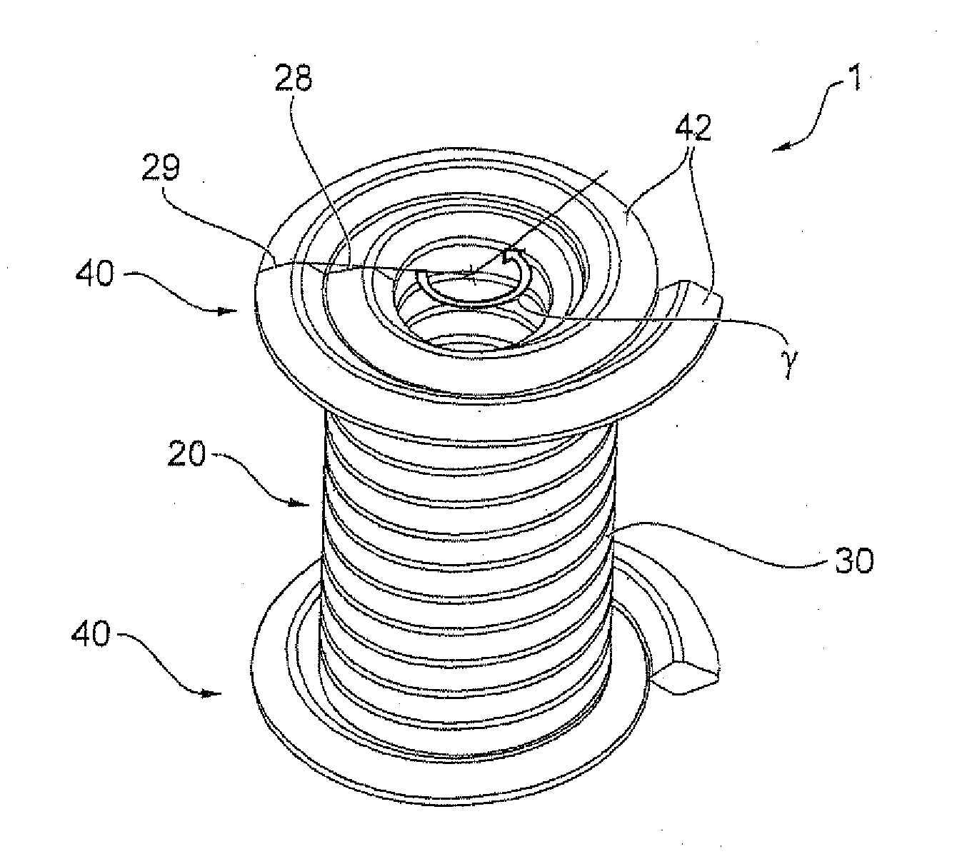
The invention is a moldable wire thread insert that can be inserted into plastic components during injection molding. The design is a cylindrical spiral with a closed wall that prevents plastic from entering the insert. The insert is secured in the component by a fastening flange that is anchored in the material of the component, preventing the insert from shifting or twisting. A unique feature of the insert is that it can be easily identified and handled automatically during production.

Problems solved by technology

The types of wire thread inserts described above as well as the different methods for their use in a component bore hole have the disadvantage that, in the course of use of the component opening with wire thread insert, it loosens in the component opening and no longer sufficiently supports the screw fastened in it or a similar fastening element.
In the worst case, the fastening element is no longer held in the component opening and can no longer fulfill its function.
This is complicated and partially constructively impossible.
Furthermore, it is disadvantageous that such a retrofitting results in standstill times e.g. of a constantly used machine.

Method used


Image

  • Moldable wire thread insert, method for its production, component with a moldable wire thread insert as well as a method for its production
  • Moldable wire thread insert, method for its production, component with a moldable wire thread insert as well as a method for its production
  • Moldable wire thread insert, method for its production, component with a moldable wire thread insert as well as a method for its production

Examples


Embodiment Construction

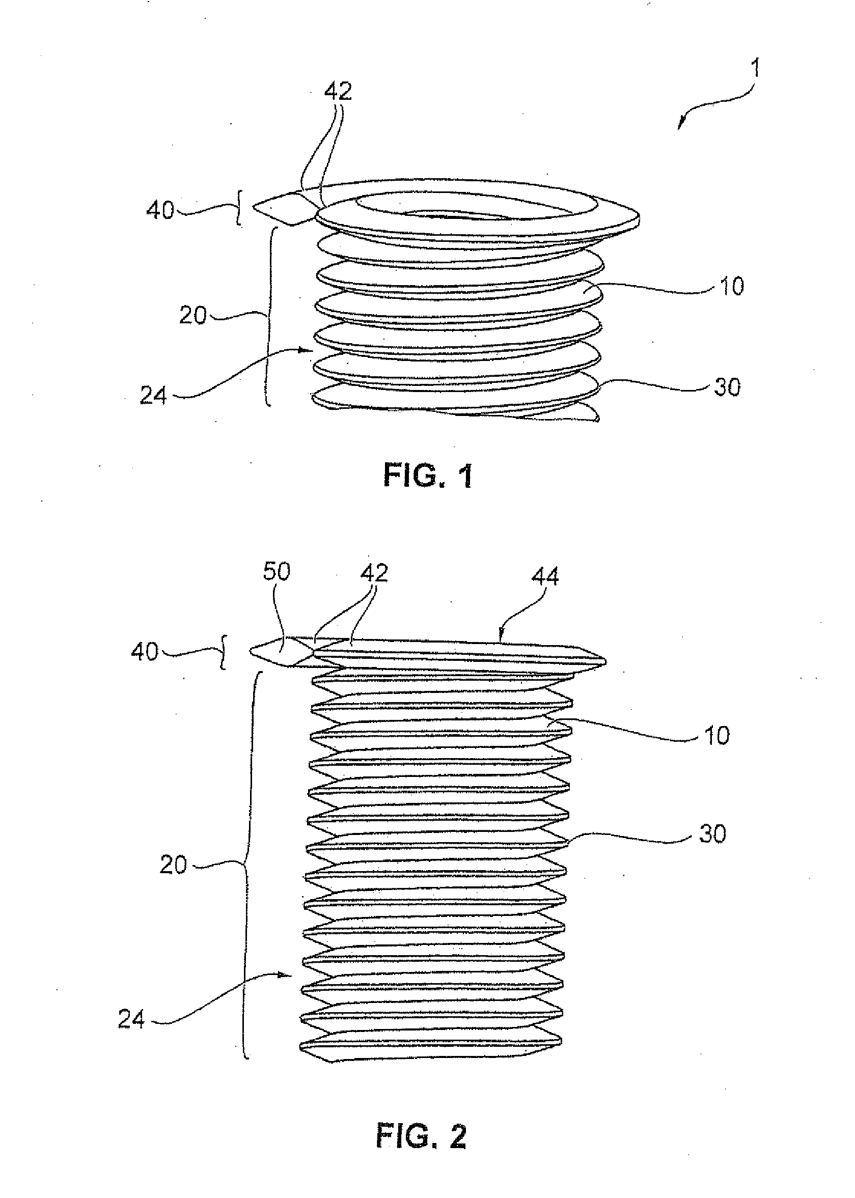
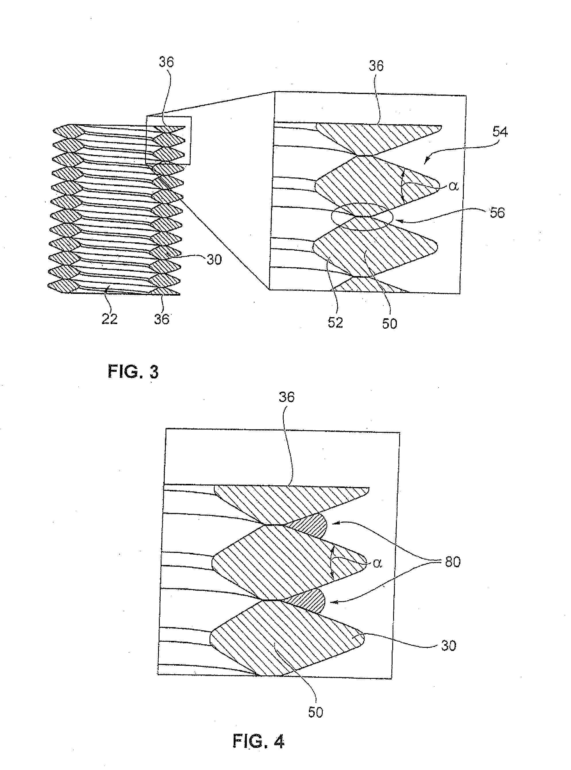
[0048]FIG. 1 shows a first preferred embodiment of a moldable wire thread insert 1. The wire thread insert 1 serves to reinforce screw-in openings of a component in order to avoid a mechanical overload of a component material during screwing in of a fastening element. For this purpose, the wire thread insert 1 comprises a cylindrical spiral 20. The cylindrical spiral 20 is spirally wound during the production of the wire thread insert 1 from a wire 10 (S1). The coils 30 wound with a certain slope of the cylindrical spiral 20 form a standard thread on the radial inner wall 22 of the cylindrical spiral 20. In accordance with different preferred embodiments, this standard thread is a metric or an imperial thread. The thread designed on the radial inside 22 of the cylindrical spiral 20 is determined through a cross-section 50 of the wire 10 and through the arrangement, in particular the slope, of the neighboring coils 30.

[0049]Since the wire thread insert 1 is moldable into a component ...


PUM


Abstract

A moldable wire thread insert for reinforcing a screw-in opening of a component has the following characteristics: a cylindrical spiral made of a helically, wound wire, the neighboring coils of which are arranged such that a closed cylindrical spiral wall is present, while at least one end of the cylindrical spirals has a fastening flange, which extends radially outwards over the cylindrical spiral wall and with which the wire thread insert is anchorable in the component and / or one end of the cylindrical spiral is designed in a planar manner in order to form an even axial front surface of the cylindrical spiral.

Description

CROSS REFERENCE TO RELATED APPLICATION[0001]This application is a divisional application of U.S. Ser. No. 13 / 499,854, filed Aug. 24, 2012, which is a national stage application of PCT / EP2010 / 006053, filed Oct. 4, 2010, which claims priority upon German Patent Application No. 10 2009 048 160.5, filed Oct. 2, 2009, the entire contents of each application herein being incorporated by reference.FIELD OF THE INVENTION[0002]The present invention relates to a moldable wire thread insert for reinforcing a screw-in opening of a component. Furthermore, the present invention is aimed at a method for producing the moldable wire thread insert as well as a component with this moldable wire thread insert. Moreover, the present invention relates to a production method for a component with this moldable wire thread insert.BACKGROUND OF THE INVENTION[0003]Wire thread inserts are generally known in the state of the art. These wire thread inserts are inserted into bore holes with internal threads in or...

Claims


Application Information

Patent Timeline
Patent Type & Authority Applications(United States)
IPC IPC(8): B65H54/00
CPCB65H54/00F16B37/127B21F3/04B29C45/14065B29C45/14549B29C2045/1495B29L2009/005B29L2031/727
Inventor GRUBERT, KLAUS FRIEDRICHSTUMPF, MICHAELSUTZ, XAVIERRINTELMANN, JOCHEN
Owner BOLLHOFF VERBINDUNGSTECHNIK GMBH
Learn More