Method of manufacturing cards that each include an electronic module and intermediate products

Active Publication Date: 2010-01-21
NAGRAVISION SA
View PDF17 Cites 5 Cited by
  • Summary
  • Abstract
  • Description
  • Claims
  • Application Information

AI Technical Summary

Benefits of technology

[0008]The present invention concerns generally a method of manufacturing at least one card, each card including an electronic module. The method provides for the provision of a frame or a plat having at least one aperture arranged for receiving at least this electronic module. This method is characterized in that at least one part of the peripheral area of said at least one aperture is deformed or crushed by the application of pressure, localised at this at least one part of the peripheral area, on said frame or said plate, so as to reduce locally the thickness of said frame or said plate in said at least one part of the peripheral area, in that said electronic module is brought opposite said at least one aperture, such that at least one zone of the electronic module is superposed on said at least one part of the peripheral area, and in that a material connection (i.e. a solid or rigid connection) is established between said at least one zone of said peripheral area of said frame or said plate and said at least one zone of the electronic module, before a resin is added to at least one side of said electronic module in a subsequent step of the method.
[0016]By selecting materials that adhere to each other, either by applying pressure, with or without the addition of heat used to melt at least partially one material or the other, or by adding adhesive between said at least one zone and said at least one part, the electronic module is sufficiently anchored in the frame to ensure that the module is held in a determined position. It is thus possible easily to transport and move a plate forming a skeleton for several cards with the electronic modules housed in a plurality of apertures, which greatly facilitates the provision of these elements in the card manufacturing installation. Moreover, at least partially fixing the edge of the module to the peripheral area of the corresponding aperture also ensures that the electronic module is held in position in the frame aperture during the entire card manufacturing method according to the invention, in particular when a resin is added.

Problems solved by technology

Such cards generally require relatively large batteries or powering means of the photovoltaic cell type.
It is not easy to integrate a relatively large electronic module, made up of various elements of variable shape and size, in a card.
Indeed, this document does not disclose how to maintain the transponder in a precise, determined position inside the aperture in the positioning frame.
However, manufacturing tolerances must be taken into account, so that it is difficult to envisage too tight a fit.
There is a further problem in addition to this problem of positioning the electronic module relative to the external contour of the card.
This problem concerns introduction of the electronic module at the centre of the card manufacturing installation.

Method used


Image

  • Method of manufacturing cards that each include an electronic module and intermediate products
  • Method of manufacturing cards that each include an electronic module and intermediate products
  • Method of manufacturing cards that each include an electronic module and intermediate products

Examples


first embodiment

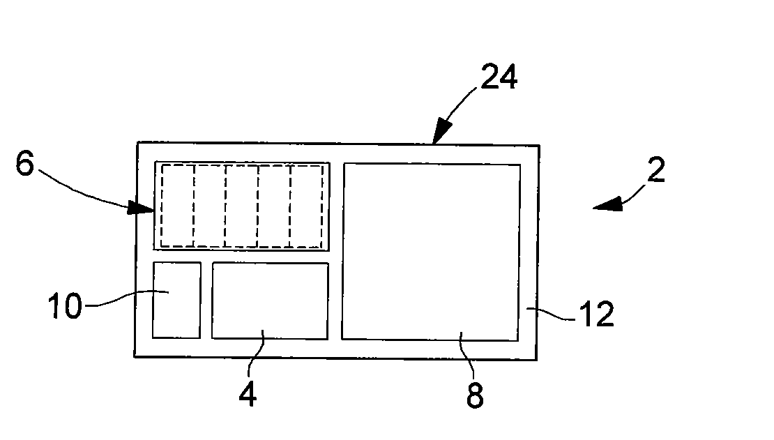
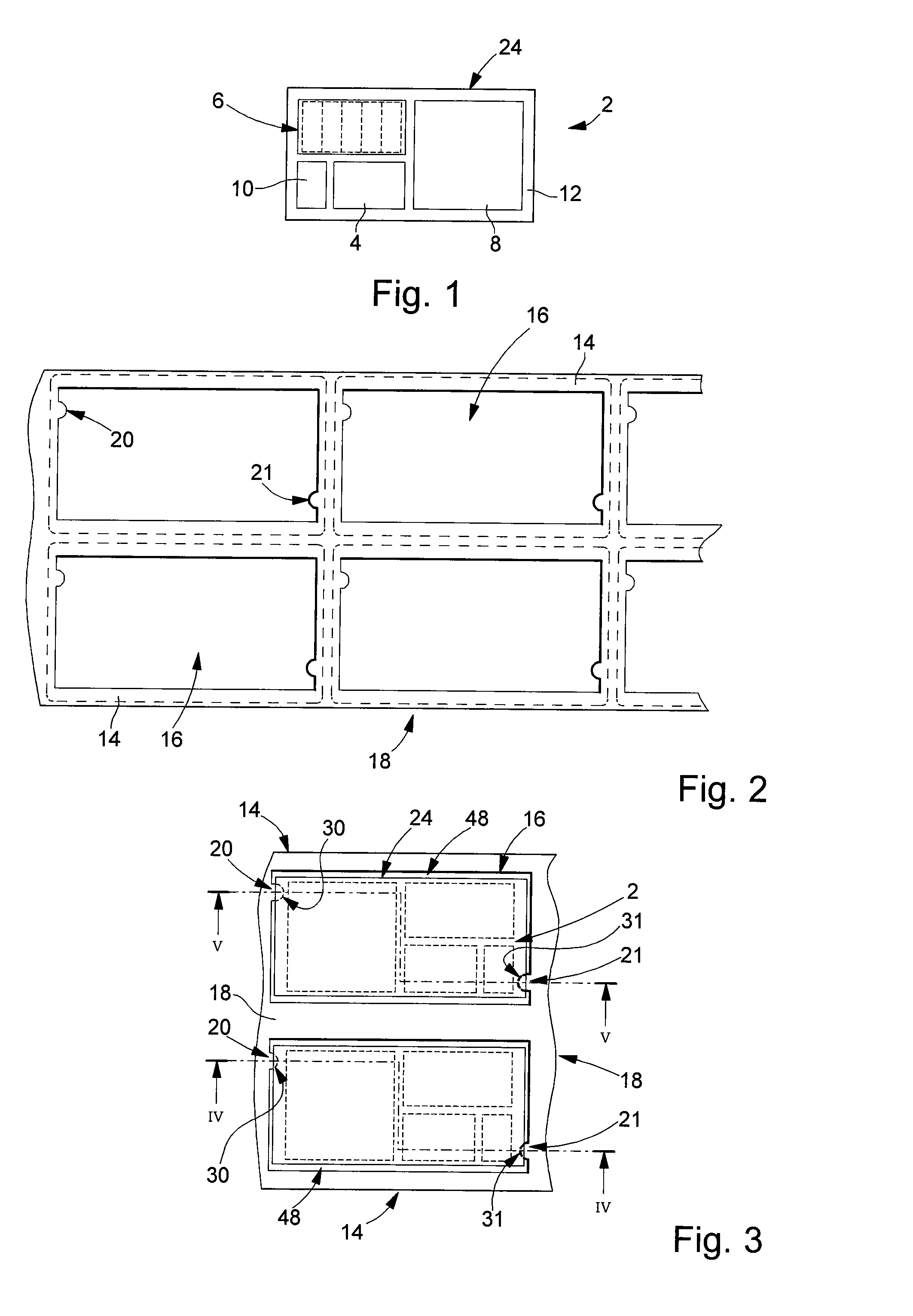
[0041]With reference to FIGS. 2 to 5, the initial steps of a first main implementation of the method according to the invention, will now be described. The manufactured cards include at least one electronic module 2, as shown schematically and solely by way of example in FIG. 1, and a frame 14, which has an aperture 16, arranged for receiving the electronic module. FIG. 2 shows a plate 18 forming a plurality of frames for a corresponding plurality of cards manufactured in accordance with the invention. Plate 18 thus includes a plurality of through apertures 16 for receiving a corresponding plurality of electronic modules. The dotted lines define the external contours of the manufactured cards, which are cut along these dotted lines once the manufacturing method has been performed for a plurality of cards in the form of a plate.

[0042]It will be noted that in FIG. 2, the final cutting operation is performed such that one frame 14 remains in the card and thus forms the median part of t...

second embodiment

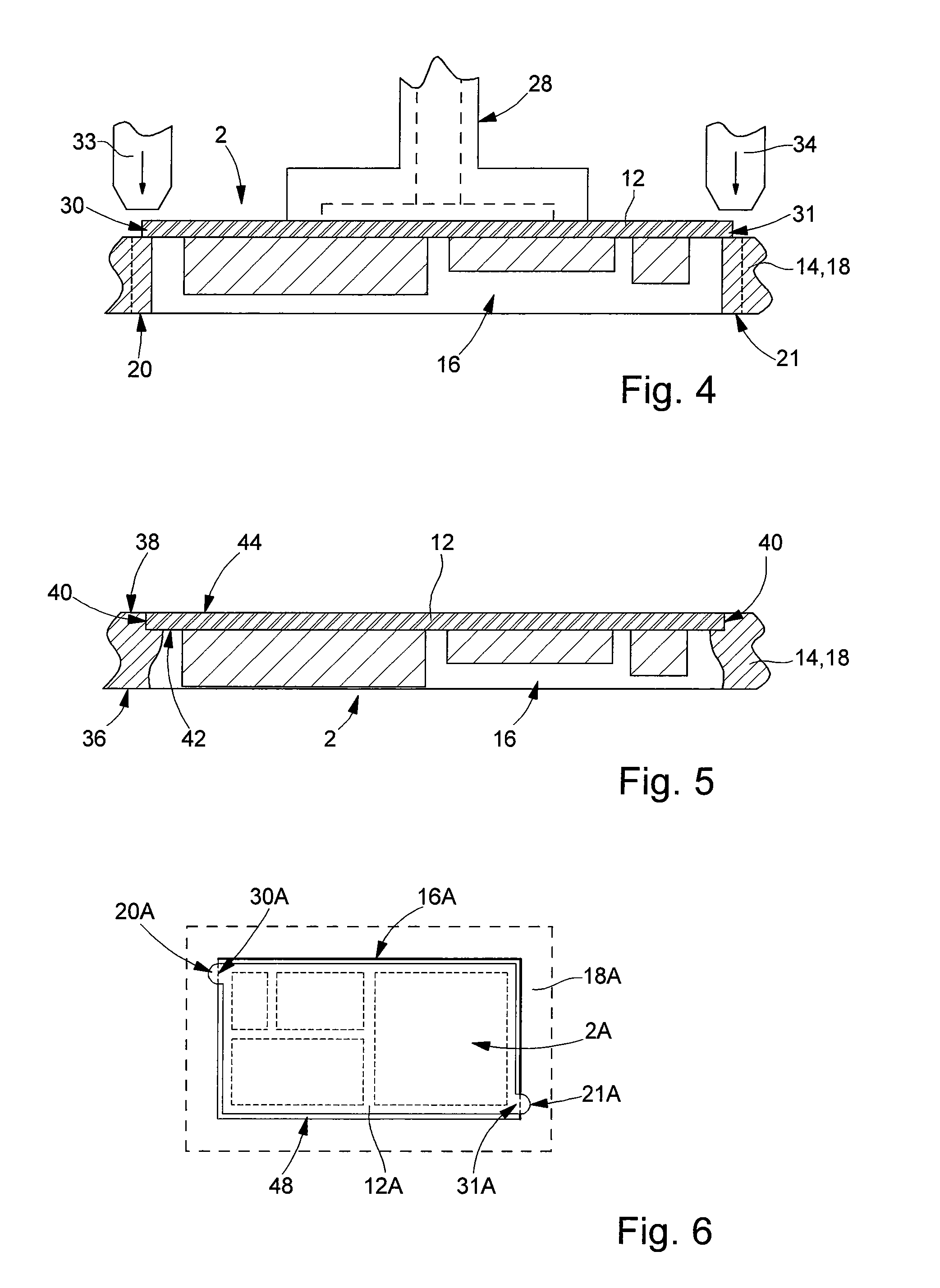
[0055]FIG. 6 shows the assembly of pierced plate 18A and electronic modules 2A. FIG. 6 shows a single aperture 16A in a plate forming a plurality of frames as shown in FIG. 2. The dimensions of a finished card are represented schematically by the outer dotted line. A similar diagram is used in the subsequent FIGS. 9, 10 and 11. Aperture 16A has a rectangular profile without any projecting portions. However, substrate 12A of module 2A has two zones 30A and 31A respectively forming two projecting parts relative to the general external profile of the module, i.e. relative to its rectangular profile. These two zones 30A and 31A on the edge of the electronic module are respectively superposed on two parts 20A and 21A in the peripheral area of aperture 16A. Electronic module 2A can be assembled to frame 14A in a similar manner to the manufacturing method according to the invention described above.

[0056]FIG. 7 shows an alternative implementation of the method. This implementation is distin...

third embodiment

[0060]FIG. 10 concerns the assembly of plate 18 and the electronic modules. Here, each aperture 16 and electronic module 2 both have a rectangular profile with no projecting parts. One dimension of support 12 is larger than the corresponding dimension of aperture 16. Thus, the two lateral zones 30C and 31C are defined by two opposite sides of the edge of module 2. These two zones are respectively superposed on the peripheral area of aperture 16 defining two edges 20C and 21C of rectangular aperture 16. Thus, as in the two other embodiments described above, the two zones 30C and 31C are pressed against parts 20C and 21C to allow module 2 to move slightly deeper into aperture 16 and to assemble module 2 to frame 14, respectively to plate 18, so that the module is arranged substantially entirely inside aperture 16, i.e. between the top and bottom surfaces of frame 14, as shown in FIG. 5. Parts 20C and 21C are preferably deformed by thermo-compression. However, as in the preceding embod...


PUM

PropertyMeasurementUnit
Fractionaaaaaaaaaa
Fractionaaaaaaaaaa
Temperatureaaaaaaaaaa

Abstract

Method of manufacturing at least one card each including an electronic module (2), this method providing a frame (14) or a plate (18) having at least one aperture (16) provided for receiving said electronic module. It is characterized in that at least one part of the peripheral area of said at least one aperture is deformed or crushed by localised application of pressure to said at least one part of the peripheral area on the frame or plate, so as to reduce locally the thickness of the frame or plate in said at least one part of the peripheral area, in that the electronic module is brought opposite the corresponding aperture so that at least one zone of the electronic module is superposed on said at least one part of the peripheral area, and in that a material connection is established between said at least one part of the peripheral area and said at least one corresponding zone of the electronic module for assembling said electronic module to the frame or plate before a resin is added at least on one side of the electronic module in a subsequent step of the method.

Description

[0001]This is a National Phase Application in the United States of International Patent Application No. PCT / EP2007 / 055320 filed Jun. 5, 2007, which claims priority on European Patent Application No. 06012550.7, filed Jun. 19, 2006. The entire disclosures of the above patent applications are hereby incorporated by reference.FIELD OF THE INVENTION[0002]The present invention concerns a method of manufacturing cards that each include an electronic module, in particular, an electronic module comprising an electronic display. Preferably, the card obtained via the method according to the invention is a bank card, in particular, conforming to the ISO standard. However, the present invention can also apply to electronic cards whose general profile is not rectangular, particularly circular cards. The present invention also concerns intermediate products obtained within the scope of the method according to the invention.BACKGROUND OF THE INVENTION[0003]Electronic cards or integrated circuit ca...

Claims


Application Information

Patent Timeline
IPC IPC(8): G06K19/077G06K19/02H05K13/00
CPCG06K19/07745H01L2924/0002Y10T29/49002H01L2924/00G06K19/077G06K19/07747H05K3/24H05K3/303
Inventor DROZ, FRANCOIS
Owner NAGRAVISION SA
Why Eureka
Try Eureka