Method for visualizing the input and display components of terminal equipment and corresponding terminal equipment

a technology of input and display components and terminal equipment, which is applied in the direction of anti-theft devices, instruments, high-level techniques, etc., can solve the problems of usability problems, user problems, and difficulty in opening keypad locks, so as to facilitate the usability of terminal equipment, reduce the power consumption of terminal equipment, and achieve simple means

Inactive Publication Date: 2007-02-20
WSOU INVESTMENTS LLC
View PDF14 Cites 5 Cited by
  • Summary
  • Abstract
  • Description
  • Claims
  • Application Information

AI Technical Summary

Benefits of technology

[0012]The present invention is intended to create a method for visualizing the input and display components of terminal equipment, which, from the user's viewpoint, will substantially facilitate the usability of terminal equipment and simultaneously also significantly reduce the power consumption of terminal equipment. The characteristic features of the invention are stated in the accompanying Claim 1. In addition to the above, the invention is also intended to create corresponding terminal equipment, which can be implemented using extremely simple means and with a negligible power consumption, compared to the prior art. The characteristic features of the terminal equipment according to the invention are stated in the accompanying Claim 8.
[0013]The use of the method according to the invention is particularly advantageous in a situation, in which the keypad of the terminal equipment is in a locked state and the user attempts to open the keypad lock, for example, in conditions with restricted lighting.
[0014]The method according to the invention is based on implementing, in the input and / or display component of the terminal equipment, an indicator effect with substantially reduced power consumption and / or a shorter duration, relative to the prior art, compared, for example to the power consumption of the system in a situation, in which the terminal equipment would switch from sleep mode to stand-by mode. The reduction can be implemented, for example, by using a short duration of the indicator effect, or by using a luminance that is substantially lower than the known level.
[0019]In addition, the use of the method according to the invention can significantly extend the stand-by time of the terminal equipment by reducing the current, compared, for example, to the manner of operation in which the illumination is activated in the input and / or display component with full brightness and an arbitrary duration.

Problems solved by technology

Users of mobile stations find the opening of the keypad lock to be problematic, especially in conditions with a restricted level of lighting.
From the viewpoint of the mobile station's user, the operation nevertheless takes a painfully long time in both cases, thus creating a usability problem.
Users who are unfamiliar with the new keypad arrangements may find difficulty in forming an image of them, for example, in conditions with restricted lighting.
Switching to stand-by mode has, as is known, a significant effect on power consumption, particularly in portable terminal equipment.
Such situations arise, for example, when the terminal equipment is in the user's pocket or correspondingly in a terminal-equipment holder attached to their belt, where the keys may be pressed unintentionally.
It is fairly obvious that all such intentional and unintentional activations will significantly affect the overall power consumption of the terminal equipment.

Method used


Image

  • Method for visualizing the input and display components of terminal equipment and corresponding terminal equipment
  • Method for visualizing the input and display components of terminal equipment and corresponding terminal equipment
  • Method for visualizing the input and display components of terminal equipment and corresponding terminal equipment

Examples


first embodiment

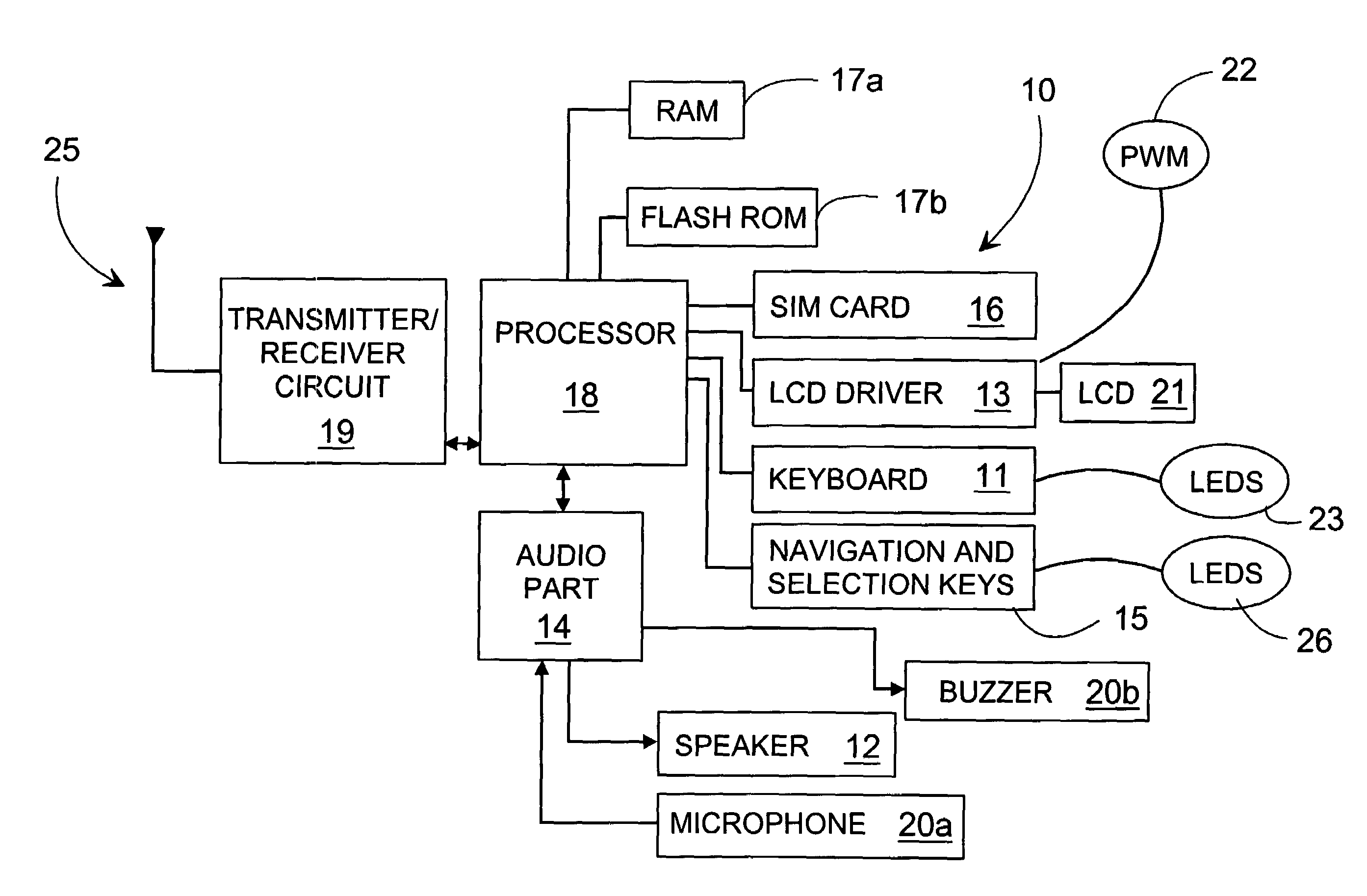
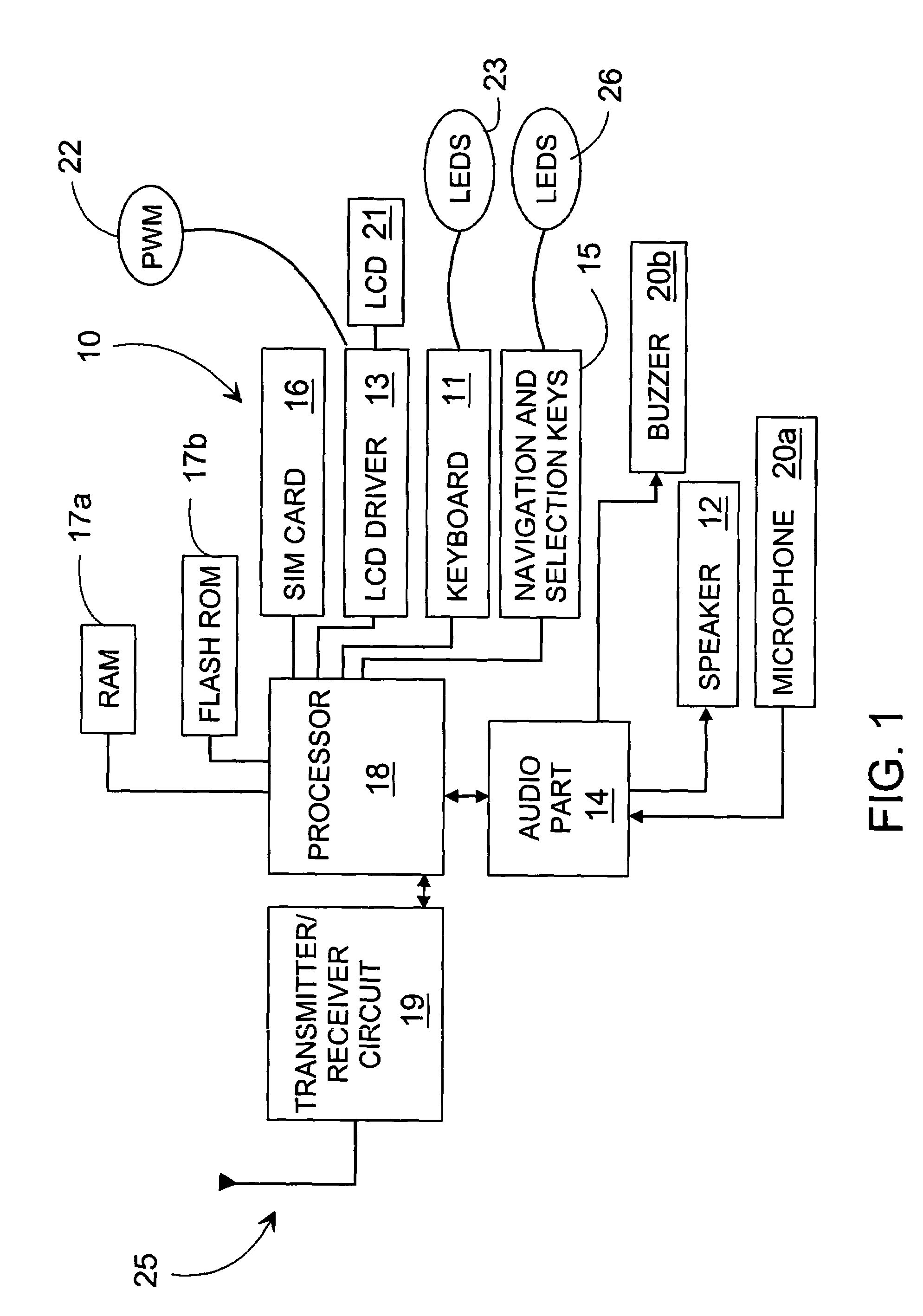
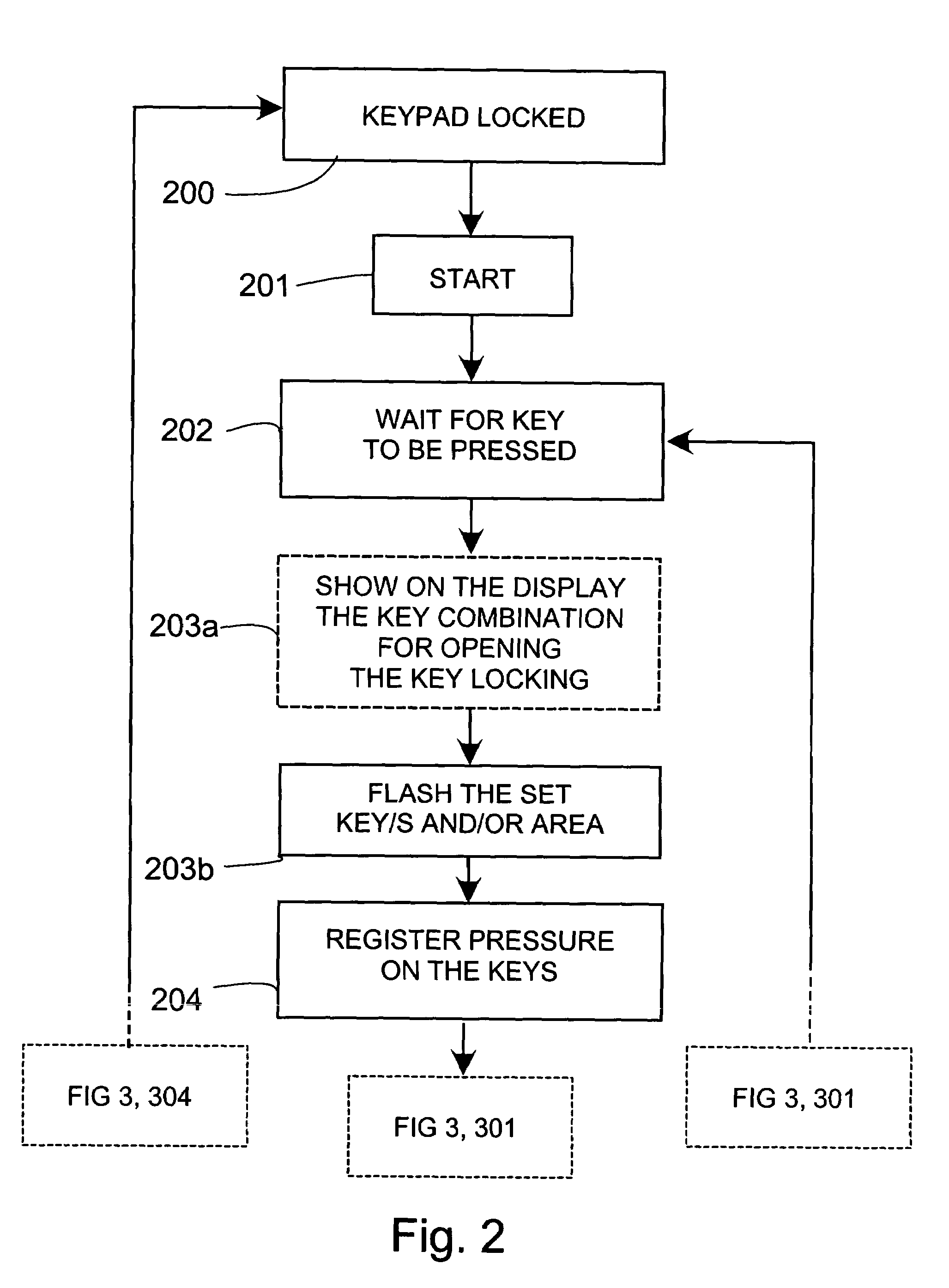
[0039] the visual indicator effect showing the location of the input component can consist of a flash, barely discernable to the user, in a set pattern, in one or more of the keys 11, 15. The flash can preferably be directed to occur only in the keys that lead to the opening of the keypad lock, for example, in the sequence of keystrokes that has been set to open the keypad lock.

second embodiment

[0040] in addition to, or alternatively instead of the above, the visual indicator effect can be implemented in the display 21 of the terminal equipment 10. A selected area of the display 21 can easily be illuminated for a short time and / or dimly, or the display can alternatively also be illuminated in its entirety.

[0041]On the other hand, according to one embodiment, the level of brightness of the indicator effect can also be selected in such a way that it consumes a negligible amount of current, compared, for example, to the amount used if the terminal equipment 10 wakes from a sleep state to a stand-by state. One example of such a barely discernable brightness can be stated as luminance of 0.1–5 cd / m2, preferably 0.5–3 cd / m2.

[0042]Luminance is a generally used measure when analysing the illumination of the keypads and displays of terminal equipment. One example of a level of barely discernable luminance can be even less than 1 cd / m2. In practice, in conditions of restricted light...


PUM


Abstract

The invention relates to a method for visualizing the input and display components of terminal equipment. The terminal equipment includes the said input component for controlling the operations of the terminal equipment and the display component. The terminal equipment (10) has at least two states, of which in the first, open, state, the terminal equipment implements the operations directed to it through the input component and in which second, locked, state, the terminal equipment does not implement the operations directed to it through the input component but instead implements an indicator effect in the input and / or the display component in order to visualize the input and / or the display component.

Description

FIELD OF THE INVENTION[0001]The present invention relates to a method for visualizing the input and display components of terminal equipment, in which the terminal equipment includes the said input component, for controlling the operations of the terminal equipment, and the display component, and in which terminal equipment there are at least two states, of which[0002]in the first, open, state, the terminal equipment implements the operations directed to it through the input component, and in which[0003]second, locked, state, the terminal equipment does not implement the operations directed to it through the input component, but instead implements an indicator effect in the input and / or the display component, in order to visualize the input and / or the display component.[0004]In addition, the invention also relates to corresponding terminal equipment.BACKGROUND OF THE INVENTION[0005]Users of mobile stations find the opening of the keypad lock to be problematic, especially in conditio...

Claims


Application Information

Patent Timeline
Patent Type & Authority Patents(United States)
IPC IPC(8): G06K5/00G06C7/02G06C25/00G06D1/00G06FG09G5/00H04M1/22H04M1/673H04M1/724H04M1/73
CPCH04W52/027H04M1/72519H04M1/673H04M1/22Y02D30/70H04M1/724
Inventor VAYRYNEN, ANTEROSAARINEN, KAJ
Owner WSOU INVESTMENTS LLC
Why Eureka
Try Eureka