
Apparatus and method for adaptive broadcast transmission

a broadcast transmission and broadcast technology, applied in the field of adaptive broadcast transmission apparatus and method, can solve the problems of inefficiency of selected schemes

Active Publication Date: 2007-02-20
GOOGLE TECH HLDG LLC
View PDF10 Cites 203 Cited by
  • Summary
  • Abstract
  • Description
  • Claims
  • Application Information

AI Technical Summary

Benefits of technology

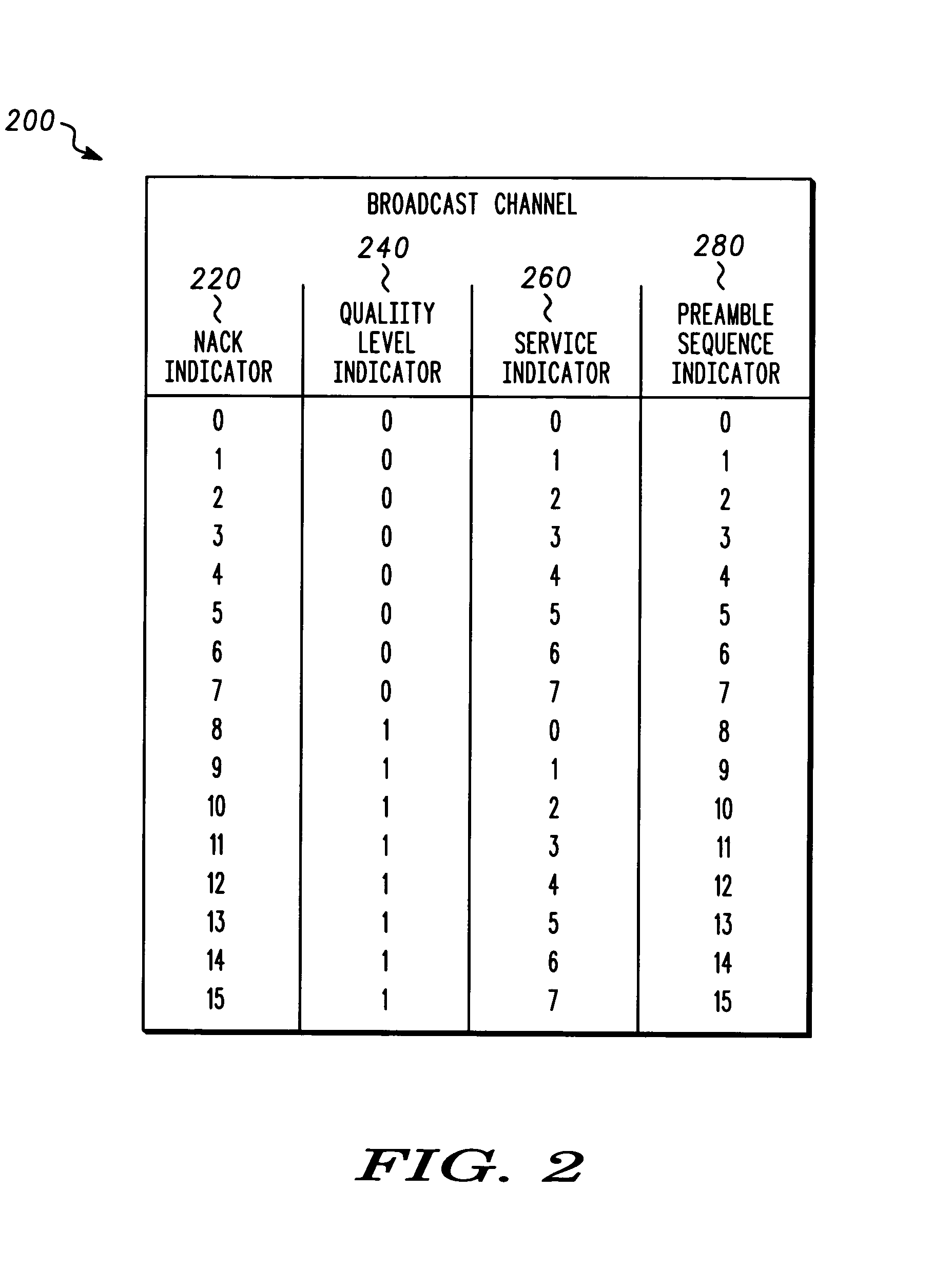
The present invention provides an apparatus and method for adaptive broadcast transmission. The invention allows for the selection of attributes of a broadcast transmission based on the quality of the broadcast transmission received by user equipment. This allows for efficient use of resources and provides better data rates for users. The invention uses a common uplink channel for negative acknowledgement signals, which can indicate the specific layer quality of a multi-layer broadcast service channel is insufficient. The invention can adapt based on detecting a selected amount of broadcast packet errors, detecting a selected amount of frame erasures, detecting a symbol error rate is above a threshold, detecting an undesirable signal to noise ratio, and / or detecting a broadcast packet error using a cyclic redundancy check code. The invention can also adjust based on a computed broadcast channel quality metric, comparing the metric to a threshold, and determining the quality is insufficient based on the result of the comparison. Overall, the invention provides an improved method for adaptive broadcast transmission that allows for better quality of service for users.

Problems solved by technology

Unfortunately, the selected scheme may not be efficient because it may use too many resources.
The selected scheme may also be inefficient because it may provide too low a data rate for the current set of broadcast receivers or because it may provide too high a data rate or too high a received error rate for the current set of broadcast receivers.

Method used


Image

  • Apparatus and method for adaptive broadcast transmission
  • Apparatus and method for adaptive broadcast transmission
  • Apparatus and method for adaptive broadcast transmission

Examples


Embodiment Construction

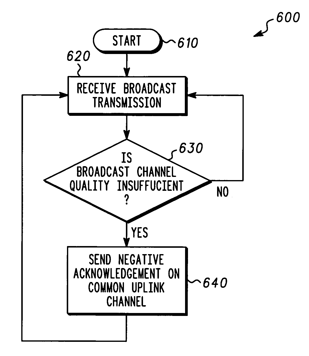
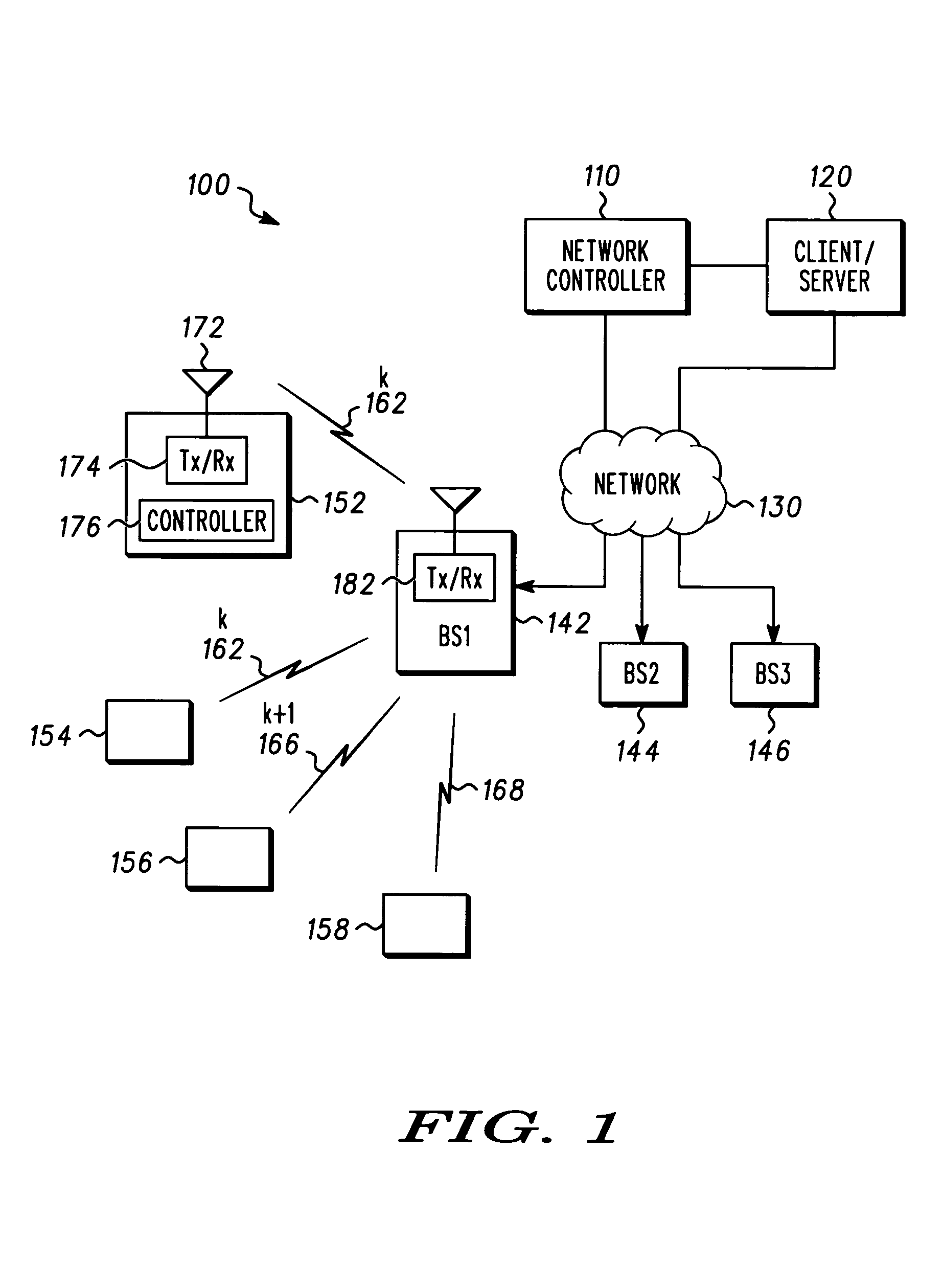
[0015]The disclosure provides an apparatus and method for adaptive broadcast transmission. According to one embodiment, the disclosure provides a method for adaptive broadcast reception in a wireless device. The method can include receiving a broadcast transmission, determining a broadcast channel quality is insufficient, and sending a negative acknowledgement signal on a common uplink channel in response to determining the broadcast channel quality is insufficient. The negative acknowledgement signal can indicate the negative acknowledgement signal is directed to a specific broadcast transmission. For example, the negative acknowledgement signal can indicate the negative acknowledgement signal is directed to a specific broadcast transmission by using at least one of a pseudo noise (PN) sequence offset, a preamble sequence selection, and a time slot assignment. Determining the broadcast channel quality is insufficient can determine the broadcast channel quality is insufficient based...


PUM


Abstract

An apparatus and method for adaptive broadcast transmission. A broadcast transmission can be received. Insufficiency of a broadcast channel quality can be determined. A negative acknowledgement signal can be sent on a common uplink channel in response to determining the broadcast channel quality is insufficient. The negative acknowledgement signal can be received on the common uplink channel at another location, the negative acknowledgement signal indicating broadcast channel quality is insufficient. The broadcast channel quality can be adjusted in response to receiving the negative acknowledgement signal.

Description

BACKGROUND[0001]1. Field[0002]The present disclosure is directed to an apparatus and method for adaptive broadcast transmission. More particularly, the present disclosure is directed to adjusting attributes of a broadcast transmission according to the quality of the broadcast transmission received by user equipment.[0003]2. Description of Related Art[0004]Presently, broadcast services can be used to send a broadcast transmission to multiple users. These broadcast services require minimal involvement from the receiver. For example, no automatic request for retransmission information, such as acknowledgement signals, or channel quality signaling is required from the receiver or used at the broadcast transmitter. While multiple modulation and coding schemes and power levels may be available to non-broadcast users, the broadcast transmission uses a fixed modulation and coding scheme. Unfortunately, the selected scheme may not be efficient because it may use too many resources. The selec...

Claims


Application Information

Patent Timeline
Patent Type & Authority Patents(United States)
IPC IPC(8): H04B17/00H04B1/707H04H1/00H04H20/42H04H60/11H04H60/91H04J13/18H04L1/00H04L1/16
CPCH04H60/11H04B17/23H04L1/1671H04L1/1692H04N7/17309H04W52/322H04L1/0026H04H20/42H04H60/91H04H2201/33H04L1/0009H04L2001/0093H04N21/44209H04N21/6131H04N21/6371H04N21/64792
Inventor LOVE, ROBERT T.BALASURIYA, SENAKABI, HAOCLASSON, BRIAN K.KELLEY, SEAN S.KRAUSE, DAVID J.
Owner GOOGLE TECH HLDG LLC
Learn More