Piezoelectricity-driven part feeder

a feeder and electric motor technology, applied in conveyors, mechanical vibration separation, operating means/releasing devices of valves, etc., can solve the problems of affecting the operation of the valve, the height of the feeder is reduced, and the reassembly is complicated, so as to achieve the effect of reducing the height, reducing the stress that acts on the vibration generator, and reducing the heigh

Inactive Publication Date: 2007-02-27
SHINKO ELECTRIC CO LTD
View PDF11 Cites 8 Cited by
  • Summary
  • Abstract
  • Description
  • Claims
  • Application Information

AI Technical Summary

Benefits of technology

[0007]The present invention has been made in view of the above-described situations. Accordingly, it is an object of the invention to provide a piezo-driven parts feeder which can be reduced in height, in which the stress that acts on a vibration generator can be restricted, sufficient amplitude can be ensured and the stress on the vibration generator can be restricted even during high-frequency driving, and the replacement of the vibration generator and the change and control of the resonance frequency can easily be performed.
[0009]With such a structure, the moving table is supported by the fixed table through the separately mounted vibration generator and support member. Thus, the height of the piezo-driven parts feeder can be decreased by adjusting the respective heights of the vibration generator and the support member and setting them. A bending load due to the static load of the moving table can be dispersed, so that the load that acts on the piezoelectric element mounted to the first elastic member can be restricted. Since the limitation to the mounting position of the vibration generator is low, an excess tensile stress is also prevented from occurring at the first elastic member.
[0010]Since the vibration generator and the support member are mounted separately, a high resonance frequency can be achieved by adjusting the spring constants such that the spring constant of the first elastic member is set small and the spring constant of the second elastic member of the support member is combined therewith. Accordingly, sufficient amplitude can be ensured and so the stress to the vibration generator can be restricted even during high-frequency driving.
[0011]The first elastic member and the second elastic member can easily be replaced separately, so that a damage to an elastic member that is not being replaced can be prevented during the replacement. The resonance frequency can easily be changed by changing the number and the spring constants of the second elastic members of the support member. The spring constants of the first elastic member and the second elastic member can be finely adjusted by combining them to a desired resonance frequency.
[0012]Consequently, a piezo-driven parts feeder can be provided which can be reduced in height, in which the stress that acts on the vibration generator can be restricted, sufficient amplitude can be ensured and the stress on the vibration generator can be restricted even during high-frequency driving, and the replacement of the vibration generator and the change and control of the resonance frequency can easily be performed.

Problems solved by technology

Furthermore, when the connecting plate is replaced for the purpose of changing resonance frequency, the elastic plate must also be replaced, not only taking a complicated labor for reassembly but also involving a great difficulty in the works of mounting the short elastic plate and the connecting plate, carrying out the setting of frequency, and fine adjustment of a mounting angle (vibration angle).
During the replacement, a large load is applied to a connecting plate and a vibrator that are not being replaced, having a tendency for the connecting plate and so on to cause plastic deformation.
Also, the elastic body is bent in S-shape in practice, causing a greater stress.
Consequently, with the piezo-driven parts feeder described in JP-A-9-110133, the elastic member having the piezoelectric element tends to be subjected to an excess tensile strength, so that also the piezoelectric element is subjected to a load, thus being reduced in life, and power is wasted, thus reducing efficiency.

Method used


Image

  • Piezoelectricity-driven part feeder
  • Piezoelectricity-driven part feeder
  • Piezoelectricity-driven part feeder

Examples


first embodiment

[First Embodiment]

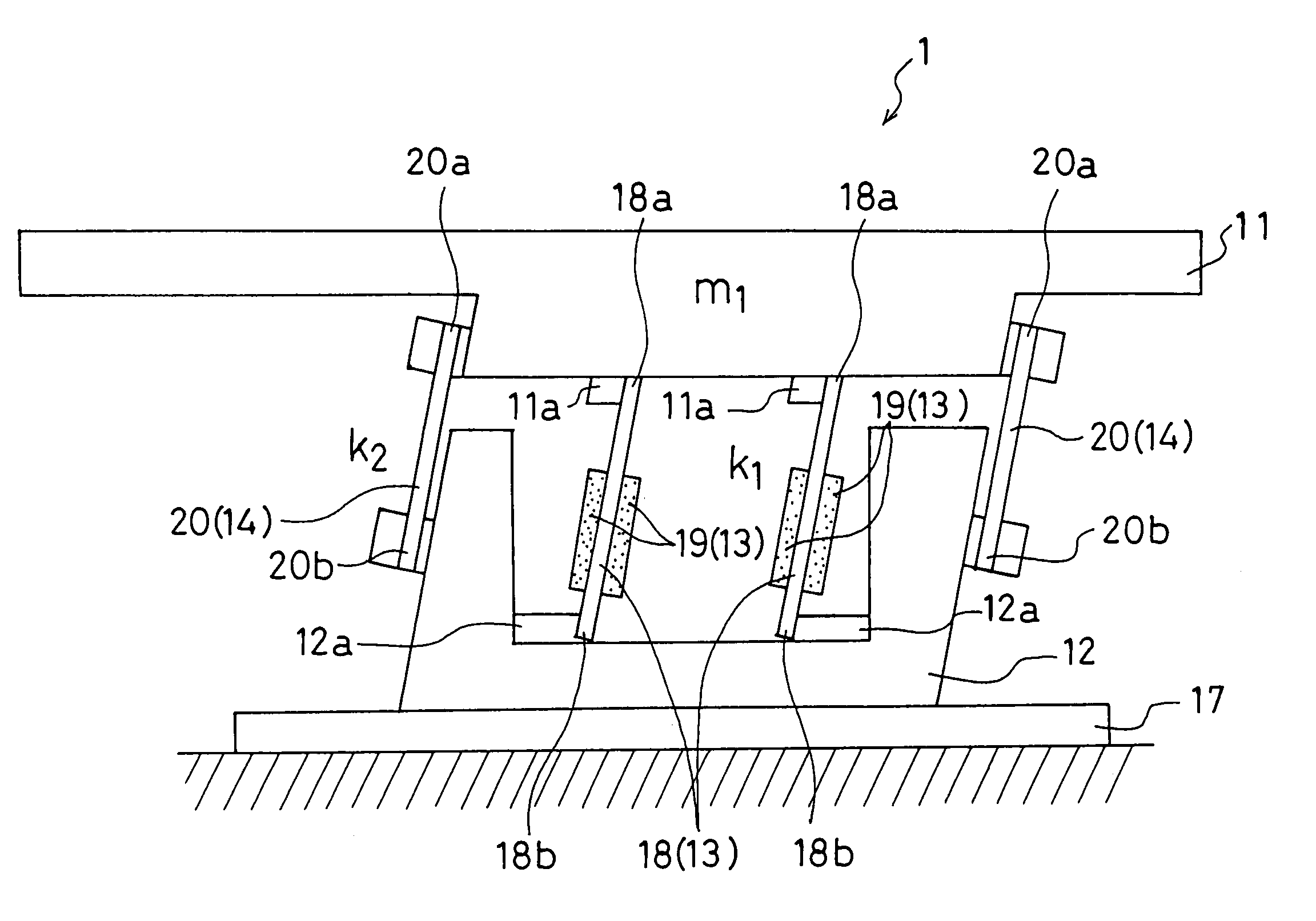
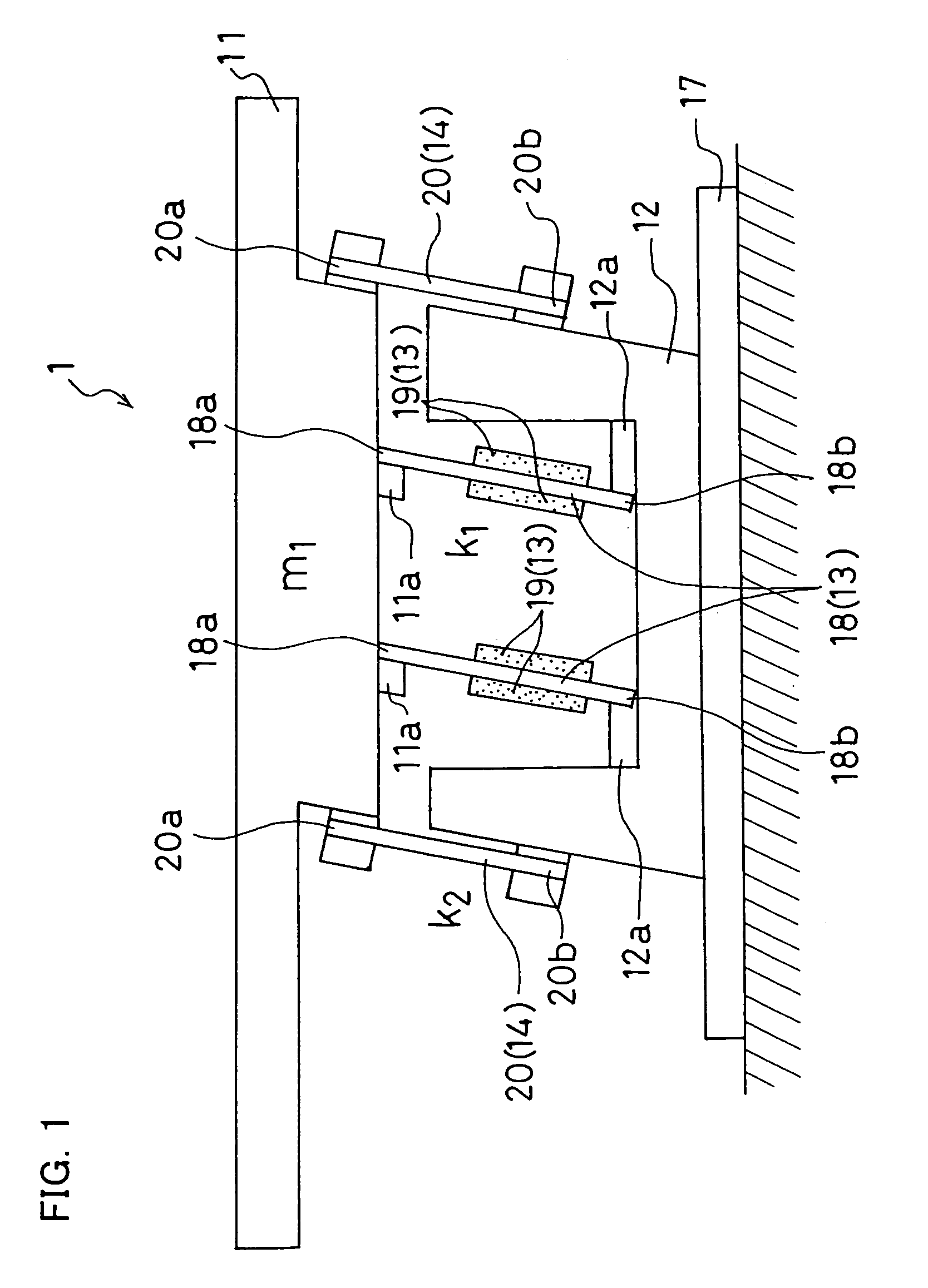
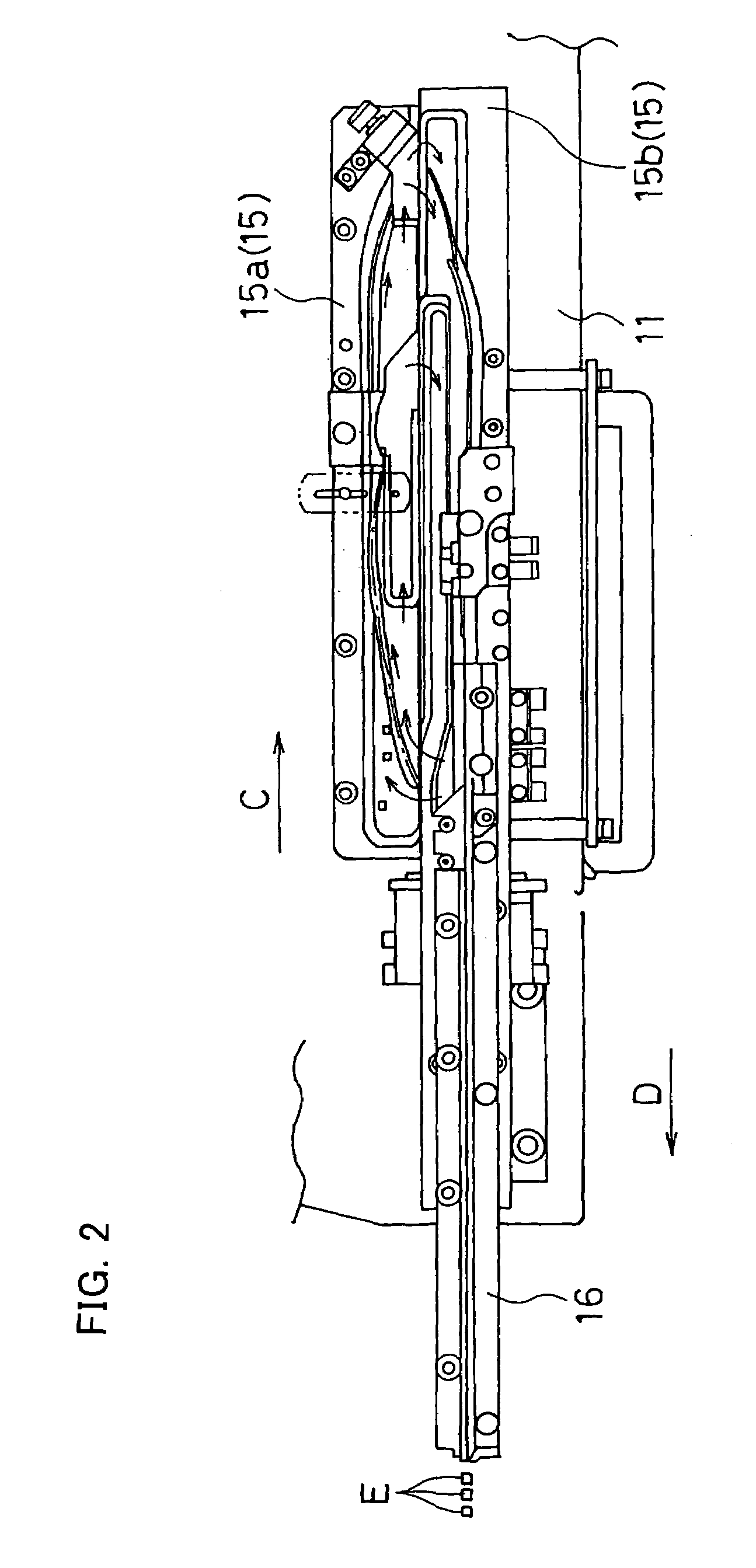
[0034]FIG. 1 schematically illustrates a piezo-driven parts feeder 1 according to a first embodiment. FIG. 2 shows the piezo-driven parts feeder 1 in plan view. In the first embodiment, a linear parts feeder will be described by way of example which conveys parts to the following process by circulating the parts into alignment while linearly vibrating a parts conveying member (a trough or the like) having a linear parts conveying track.

[0035]As shown in FIG. 1, the piezo-driven parts feeder 1 includes a moving table 11, a fixed table 12, a vibration generator 13, and a support member 14.

[0036]Referring to FIG. 2, the moving table 11 supports a parts conveying member (trough) 15 having a parts conveying track (parts conveying path) (i.e., the trough 15 is secured to the upper surface of the moving table 11). The trough 15 shown in FIG. 2 includes a return trough 15a having a track that conveys parts along the arrow C for returning the parts and a main trough 15b hav...

second embodiment

[Second Embodiment]

[0055]Referring to FIGS. 3 and 4, a piezo-driven parts feeder 2 according to a second embodiment will be described. An example of application to the linear parts feeder will be described with reference to the schematic diagram of the piezo-driven parts feeder 2 in FIG. 3. The elements of FIG. 3 similar to those of the piezo-driven parts feeder 1 according to the first embodiment are given the same numerals and their description will be omitted.

[0056]The piezo-driven parts feeder 2 has a similar structure to that of the piezo-driven parts feeder 1 but is different in the structure of a piezoelectric spring (leaf spring) 21 serving as a first elastic member. As shown in FIG. 3, the piezoelectric spring 21 in the piezo-driven parts feeder 2 is formed substantially in L-shape. One side (a first side) 22 of the L-shape is arranged substantially perpendicular to the moving table 11 and the fixed table 12, while the other side (a second side) 23 of the L-shape is mounted...

third embodiment

[Third Embodiment]

[0060]A piezo-driven parts feeder 3 according to a third embodiment will be described.

[0061]FIG. 5 schematically shows the piezo-driven parts feeder 3 in perspective. The piezo-driven parts feeder 3 has the similar structure to that of the piezo-driven parts feeder 2 according to the second embodiment but is different in that it is applied to the bowl parts feeder, not to the linear parts feeder.

[0062]The piezo-driven parts feeder 3 includes a moving table 26, a fixed table 27, a vibration generator 28, and a support member 29. The vibration generator 28 has a piezoelectric spring 30 serving as a first elastic member and a piezoelectric element 31. The support member 29 has a support spring 32 serving as a second elastic member. The piezoelectric spring 30 is formed in L-shape and one side (a first side) of the L-shape is arranged approximately perpendicular to the moving table 11 and the fixed table 12, while the other side (a second side) is arranged almost in pa...


PUM


Abstract

A moving table supports a parts conveying member. A fixed table is disposed below the moving table and supports the moving table so as to freely vibrate the moving table through a vibration generator. The vibration generator includes a first elastic member and a piezoelectric element mounted to the first elastic member. One end of the first elastic member is fixed to the moving table and the other end is fixed to the fixed table. A support member includes a second elastic member. One of the second elastic member is fixed to the moving table and the other end member is fixed to the fixed table. Accordingly, the piezo-driven parts feeder can be reduced in height, the stress that acts on the vibration generator can be restricted, sufficient amplitude can be ensured and the stress on the vibration generator can be restricted even during high-frequency driving, and the replacement of the vibration generator and the change and control of the resonance frequency can easily be performed.

Description

BACKGROUND OF THE INVENTION[0001]1. Technical Field of the Invention[0002]The present invention relates to a piezo-driven parts feeder for conveying parts in alignment by generating vibration to a parts conveying member having a parts conveying track with a vibration generator including an elastic member having a piezoelectric element mounted thereto.[0003]2. Description of the Prior Art[0004]Piezo-driven parts feeders are well known which convey parts in alignment by generating vibration to a parts conveying member including a parts conveying track with a vibration generator having a piezoelectric element mounted thereto. For example, ones disclosed in JP-A-62-4118 and JP-A-9-110133 are known. The piezo-driven parts feeder described in JP-A-62-4118 aims to increase the amplitude of vibration applied to a parts conveying member by connecting an elastic plate (elastic member) of a vibrator (vibration generator) and a conveyer (parts conveying member) together with a connecting plate ...

Claims


Application Information

Patent Timeline
Patent Type & Authority Patents(United States)
IPC IPC(8): B65G27/08B65G27/24
CPCB65G27/24B06B1/045B65G27/08B65G27/18F16K31/007G01N3/38
Inventor NARUKAWA, SHUUICHIKIMURA, TETSUYUKI
Owner SHINKO ELECTRIC CO LTD
Why Eureka
Try Eureka