Light-conductive board and a rear light module using the light-conductive board

a technology of light-conductive boards and light-conductive boards, which is applied in the direction of planar/plate-like light guides, lighting and heating apparatus, instruments, etc., can solve the problem that the method cannot fully improve the formation of grey areas, and achieve the effect of eliminating grey areas

Inactive Publication Date: 2007-02-27
RADIANT OPTO ELECTRONICS
View PDF9 Cites 42 Cited by
  • Summary
  • Abstract
  • Description
  • Claims
  • Application Information

AI Technical Summary

Benefits of technology

[0012]Still another object of the present invention is to provide a light-conductive board and a rear light module using the light-conductive board, wherein the light-emitting face adjacent to the light-entering recessed board can extend the incident light angle of the lamp source to eliminate the grey area due to excessive small lamp source.

Problems solved by technology

This method cannot fully improve the formation of the grey region 35.

Method used


Image

  • Light-conductive board and a rear light module using the light-conductive board
  • Light-conductive board and a rear light module using the light-conductive board
  • Light-conductive board and a rear light module using the light-conductive board

Examples


Embodiment Construction

[0027]The following descriptions are of exemplary embodiments only, and are not intended to limit the scope, applicability or configuration of the invention illustration for implementing exemplary embodiments of the invention. Various changes to the described embodiments may be made in the function and arrangement of the elements described without departing from the scope of the invention as set forth in the appended claims.

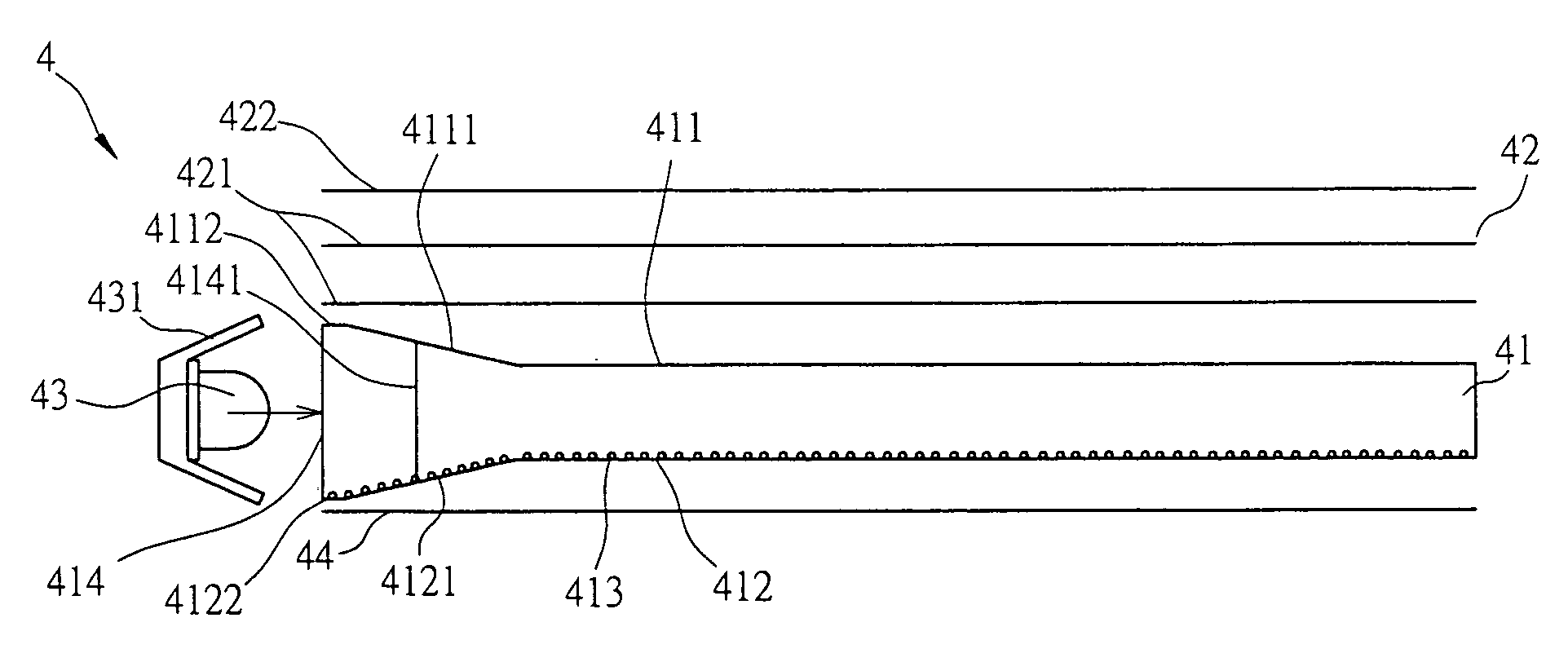
[0028]Referring FIG. 7, there is shown a rear light module 4 including a light conductive board 41, an optical film 42, and a LED lamp source 43. The light-emitting face 411 of the light-conductive board 41 is mounted with the optical film 42 having one or more than one divergence lens 421 and a convergence lens 422. The reflective face 412 of the light conductive board 41 is provided with a plurality of light-conductive points 413, and a reflective board 44 is adhered at the external thereof, and at the same time, one side of the light conductive board 41 is pro...


PUM


Abstract

A light-conductive board and a rear light module using the light-conductive board is disclosed. The light-conductive plate having a light-emitting face, a light-reflecting face, and at least a light-entering face and the light-reflecting plate adhered onto the external of the light-reflecting face of the light-conductive board, an optical film including a divergent lens and a convergent lens mounted onto the external of light-emitting face of the light-conductive board, a lamp reflector which encloses a lamp source, and the light-entering face of the light-conductive board corresponding to the circumferential edge of the light-entering recessed region of the lamp source adjacent to the light-emitting face or one of the face of the reflection face at least forms into a protruded section.

Description

BACKGROUND OF THE INVENTION[0001](a) Technical Field of the Invention[0002]The present invention relates to a light-conductive board and a rear light module, and in particular to a light-conductive board having a light-entering recess section circumferential edge mounted with a protruded section, facilitating the application of rear light module to output even and high hue light source so as to improve the light output efficiency of the entire module.[0003](b) Description of the Prior Art[0004]The majority of LCDs consists of a displaying panel and a rear light module. The rear light module is an essential element being a light source. Thus, it is an important element within the LCD.[0005]FIG. 1 shows a conventional rear light module 1 including a conductive light board 11, an optical film 12 and a LED light source 13. FIG. 2 shows the application of the rear light module 1. The light source of LED lamp source 13 is affected by the reflector 131 and the light source will enter the l...

Claims


Application Information

Patent Timeline
Patent Type & Authority Patents(United States)
IPC IPC(8): F21V7/04F21V8/00
CPCG02B6/002G02B6/0046G02B6/0036G02B6/0031
Inventor CHEN, YUNG-JENHOU, PEI-FENTSENG, KUAN-LINGCHU, YEN-CHUANWANG, YING-FU
Owner RADIANT OPTO ELECTRONICS
Why Eureka
Try Eureka