Method and apparatus for banding artifact detection

Inactive Publication Date: 2011-06-02
THOMSON LICENSING SA
View PDF18 Cites 18 Cited by
  • Summary
  • Abstract
  • Description
  • Claims
  • Application Information

AI Technical Summary

Benefits of technology

[0009]According to one aspect of the present invention, the method for detecting banding artifacts includes screening candidate banding artifact areas in a digital image based on at least one feature of the areas, filtering the screened candidate banding artifact are

Problems solved by technology

This is often a manual and subjective process that requires substantial experience, time and effort affecting the production time and budget.
It is also subject to inconsistency due to different visual evaluation standards imposed by different evaluators.

Method used


Image

  • Method and apparatus for banding artifact detection
  • Method and apparatus for banding artifact detection
  • Method and apparatus for banding artifact detection

Examples


Embodiment Construction

[0019]The present principles provides a method and apparatus to (i) find the locations of the banding artifacts, (ii) determine the strength of the banding artifact per block, and (iii) determine overall banding artifact strength per picture.

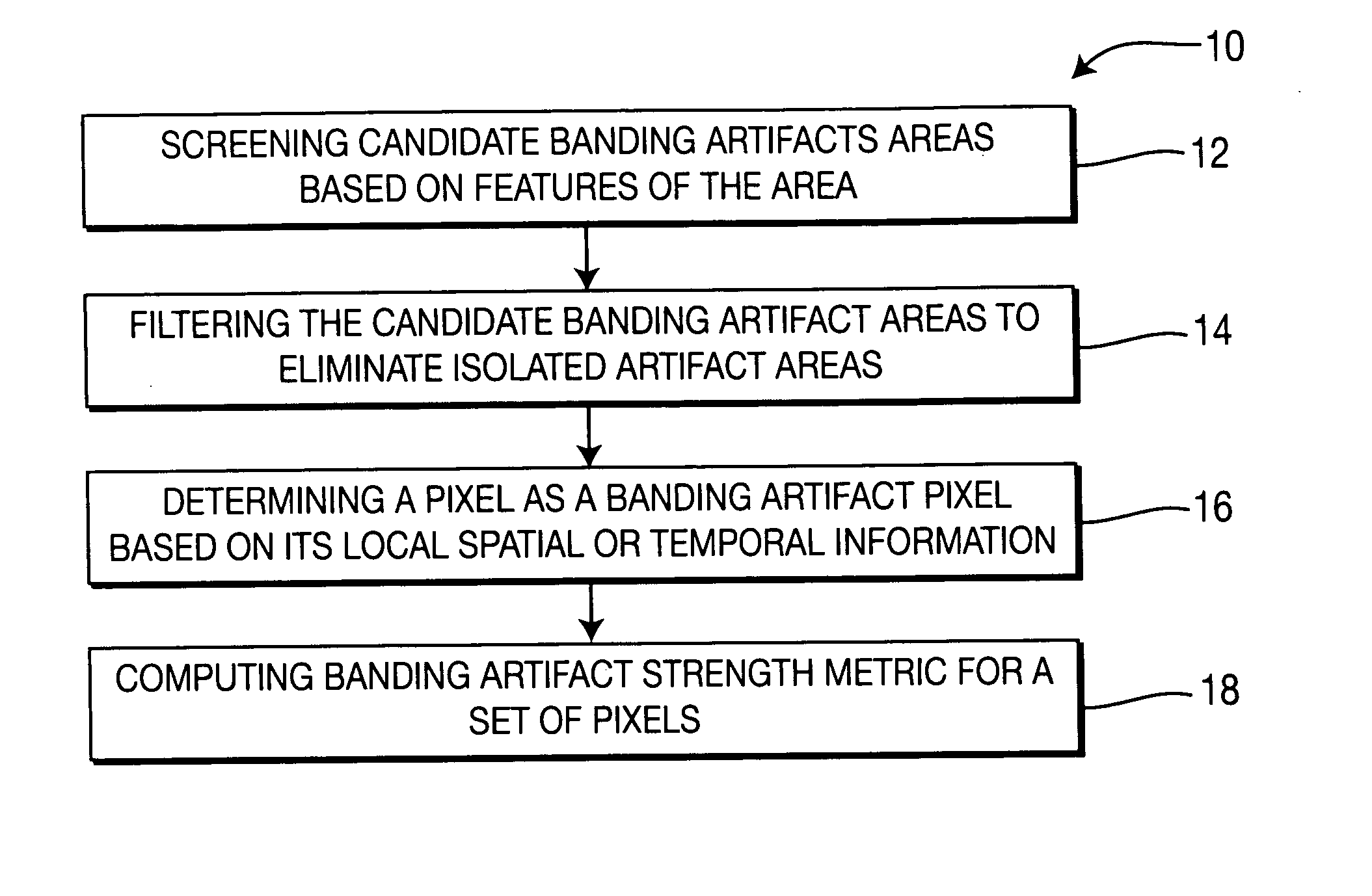
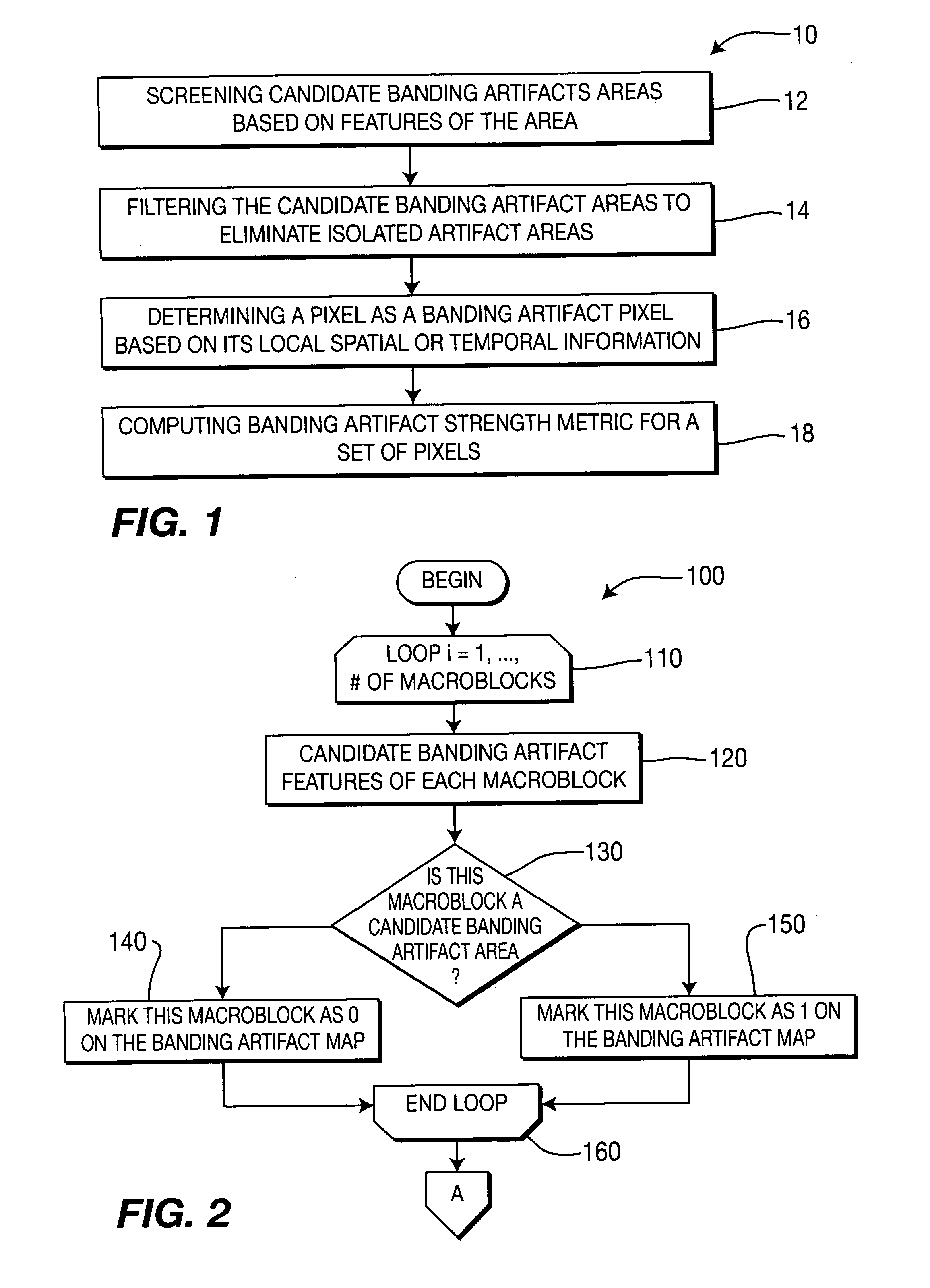
[0020]FIG. 1 shows a high level flow diagram of the banding artifact detection method 10 according to an implementation of the present principles. In this implementation, the banding artifact detection is done by first screening (12) the targeted picture or pictures and locating the candidate banding artifact areas. The candidate banding artifact areas are then filtered (14) to eliminate the isolated areas. Each pixel in the candidate areas is then subject to a local spatial or temporal context evaluation to reduce false detection. A decision is then made (16) on a pixel level regarding whether a pixel is part of a banding artifact area. The pixel level decision can be further transformed or computed (18) to determine a banding artifact metric t...


PUM


Abstract

A method and apparatus for detecting banding artifacts in digital images and video contents. The method operates to (i) find the locations of the banding artifacts, (ii) determine the strength of the banding artifact per block, and (iii) determine overall banding artifact strength per picture. The banding artifact detection and strength assignment is done by first finding areas that are prone to banding artifact and then considering the local characteristics of the area to reduce the false detection. The banding artifact strength of a picture is determined by considering the size and the strength of the artifact areas in this picture as well as the artifact strength in the neighboring pictures.

Description

BACKGROUND[0001]1. Technical Field[0002]Principles of the present invention relate to processing digital images and video content. More particularly, they relate to detecting banding artifacts in digital images and video content.[0003]2. Description of the Related Art[0004]Non-real time image and video processing applications such as DVD authoring, aim at achieving the best possible visual quality from an image and video processor. To that goal, the processed images or video contents are reviewed to identify pictures with artifacts. This is often a manual and subjective process that requires substantial experience, time and effort affecting the production time and budget. It is also subject to inconsistency due to different visual evaluation standards imposed by different evaluators. In common practice, detected pictures are post-processed or re-encoded with fine-tuned parameters and subject to further review. The post-processing or re-encoding algorithms can tune their parameters b...

Claims


Application Information

Patent Timeline
IPC IPC(8): H04N7/12G06T5/00G06T7/00H04N19/146
CPCG06T7/0002G06T5/002G06T2207/10016G06T2207/20032H04N19/176H04N19/115H04N19/86H04N19/124H04N19/136H04N19/152H04N19/154H04N19/17H04N19/61G06T5/00G06T7/00H04N19/146
Inventor LI, ZHENABBAS, ADEELLU, XIAOANGOMILA, CRISTIN
Owner THOMSON LICENSING SA
Why Eureka
Try Eureka