Printer with cutter

a technology of printing machine and cutter, which is applied in printing, inking apparatus, metal working apparatus, etc., can solve the problems of difficult to meet the need for a reduction in size, difficult to compactly configure the thermal printer, and needlessly long recording sheets to be difficult to handle as tickets, etc., to achieve convenient and fast movement, prevent jamming, and compact structure

Active Publication Date: 2009-11-12
SEIKO INSTR INC
View PDF2 Cites 21 Cited by
  • Summary
  • Abstract
  • Description
  • Claims
  • Application Information

AI Technical Summary

Benefits of technology

[0036]In the printer with a cutter according to the present invention, when the recording sheet gets in between the fixed blade holder and the platen roller during the printing for some reason, the recording sheet is temporarily smoothly guided along the another surface to automatically start moving toward the downstream side in the rotating direction of the platen roller. Then, the recording sheet is transferred to the guide table while moving. Then, the transferred recording sheet is guided toward the downstream side in the rotating direction of the platen roller while moving on the guide table in a sliding manner to move into the gap between the opposed surface of the holder support and the platen roller. In particular, the guide table is formed to extend from the holder support beyond the boundary with the fixed blade holder toward the another

Problems solved by technology

However, the following problems still remain for the conventional thermal printer 100.
Therefore, because the thermal printer is constituted by the combination of a plurality of units, there is no easy way to compactly configure the thermal printer.
Accordingly, it is difficult to meet the need for a reduction in size.
Therefore, the

Method used


Image

  • Printer with cutter
  • Printer with cutter
  • Printer with cutter

Examples


Embodiment Construction

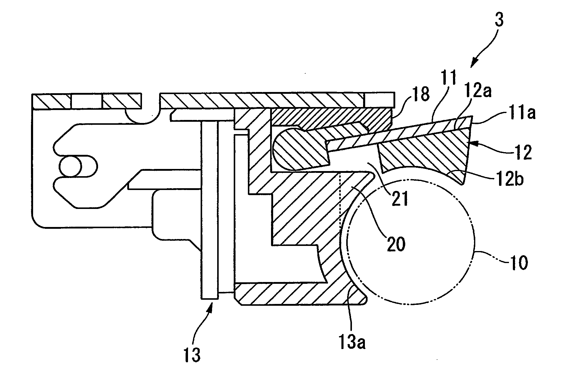
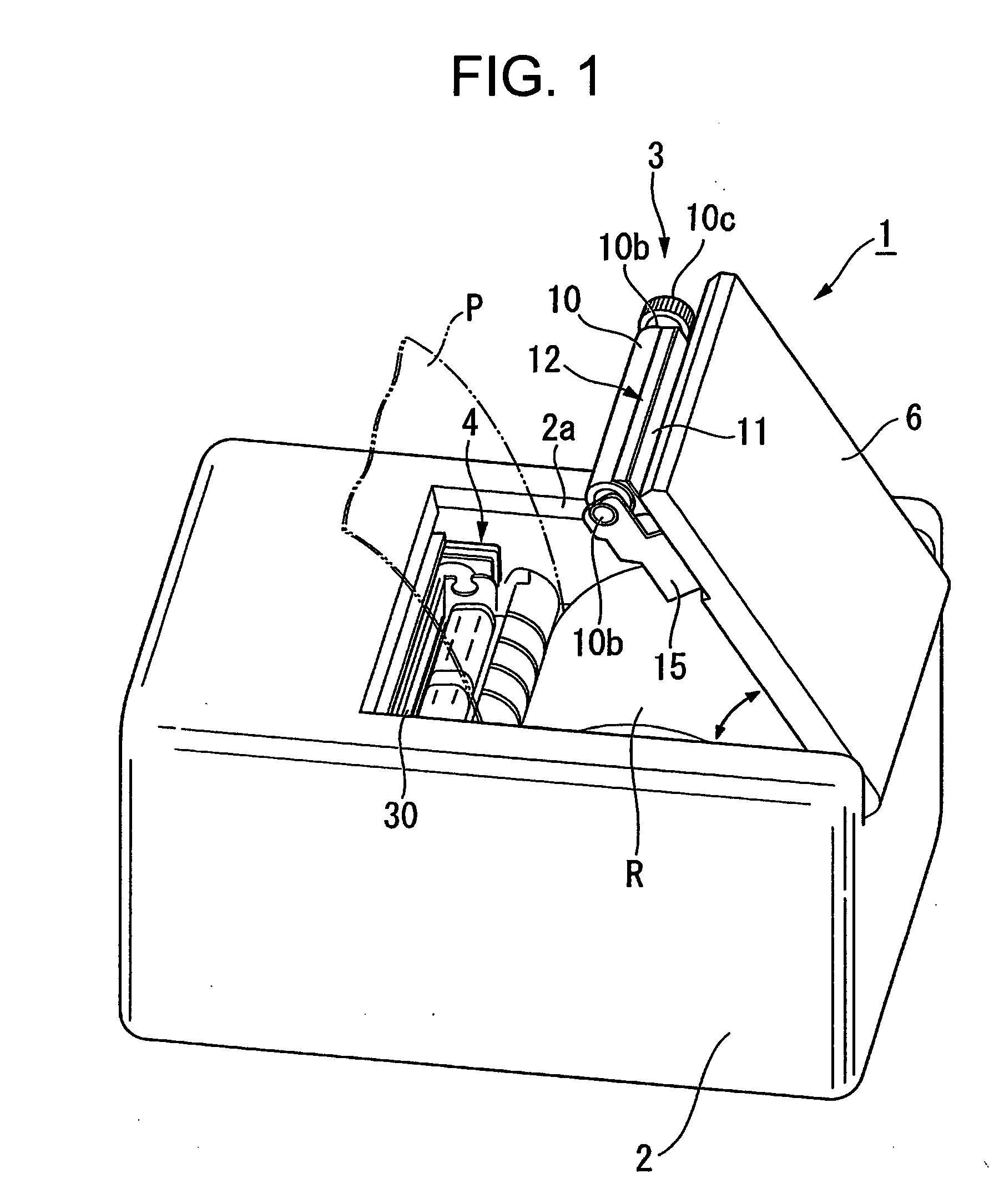
[0058]Hereinafter, the printer with a cutter according to a first embodiment of the present invention is described with reference to FIGS. 1 to 11. In this embodiment, a thermal printer is exemplified as one example of a printer with a cutter.

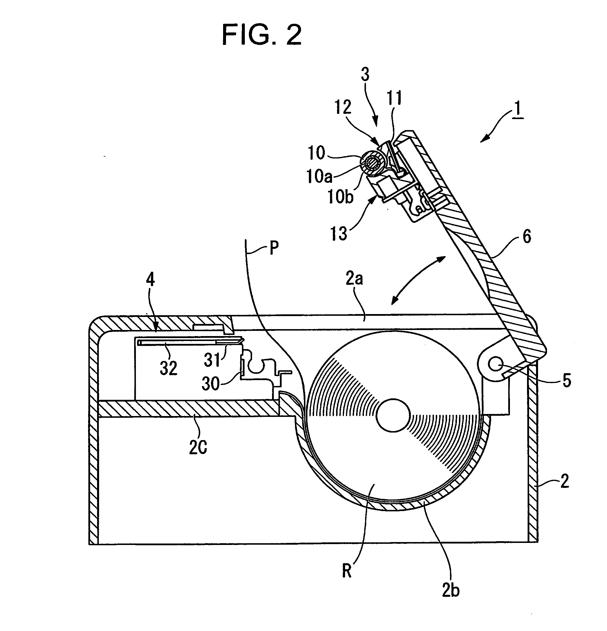
[0059]A thermal printer 1 of this embodiment is a printer that can appropriately cut a recording sheet P pulled out from a paper roll R after performing printing on the recording sheet P to use as a ticket, a receipt, and the like, and mainly includes a casing 2, a platen unit 3, and a main body unit 4, as illustrated in FIG. 1 and FIG. 2.

[0060]The casing 2 is a casing molded from injection molding of plastic such as polycarbonate and the like or a metal material, and is formed to a box-shape with an insertion port 2a opened at the upper surface. A placement table 2b for placing the paper roll R inserted from the insertion port 2a is arranged in the interior of the casing 2. The placement table 2b is formed to be curved in an arcuate shape, and...


PUM


Abstract

an object of the present invention is to provide a printer with a cutter, which has a compact structure to allow for the reduction in size and is capable of performing printing while eliminating an unprinted area as much as possible and of easily performing recovery without wasting a recording sheet even if a paper jam occurs during the printing. Provided is a printer with a cutter including a platen roller 10 for feeding a recording sheet, a fixed blade 11 provided adjacent to the platen roller, a fixed blade holder 12 having one surface 11a for fixing the fixed blade thereon and another surface 11b being opposed to an outer peripheral surface of the platen roller, and a holder support 13 having an opposed surface 13a being opposed to the outer peripheral surface of the platen roller on a downstream side of the holder in a rotating direction of the platen roller, for rockably supporting the fixed blade holder, in which the another surface of the fixed blade holder is formed to be curved along the outer peripheral surface of the platen roller and guides the recording sheet toward the downstream side in the rotating direction of the platen roller when the recording sheet gets into a gap between the fixed blade holder and the platen roller.

Description

BACKGROUND OF THE INVENTION[0001]1. Field of the Invention[0002]The present invention relates to a printer with a cutter capable of appropriately cutting a recording sheet pulled out from a paper roll after performing printing on the recording sheet.[0003]2. Description of the Related Art[0004]Nowadays, a great number of various types of thermal printers, which perform printing by pressing a heated thermal head against a special recording sheet that changes color when heat is applied thereto, are provided. In particular, use is suitably made in printing of various labels, receipts, tickets, and the like because smooth character printing and colorful graphic printing are possible without using toner, ink, and the like.[0005]As the thermal printers, printers provided with a cutter mechanism for cutting the printed recording sheet are typically known (see Patent Documents JP 2007-38367 A and JP 11-123692 A). The cutter mechanism is normally set (auto cutter) to automatically cut the re...

Claims


Application Information

Patent Timeline
IPC IPC(8): B41J11/66
CPCB26D1/085B26D7/00B41J2202/31B41J2/32B41J11/706B26D7/2628B41J11/04
Inventor KAWAGUCHI, KOUJI
Owner SEIKO INSTR INC
Why Eureka
Try Eureka