Endoscope attachment and endoscope

a technology of endoscope and endoscope, which is applied in the field of endoscope attachment, can solve the problems of difficult surface inspection by the physician, high possibility of overlooking lesions, and high possibility of overlooking lesions, and achieve the effects of reducing the number of blind spots, easy expansion of the functions, and low cos

Inactive Publication Date: 2011-04-12
OSAKA UNIV
View PDF38 Cites 19 Cited by
  • Summary
  • Abstract
  • Description
  • Claims
  • Application Information

AI Technical Summary

Benefits of technology

[0023]According to the endoscope attachment of the present invention, it is possible to realize an endoscope attachment which enables an endoscope to eliminate any blind areas and prevent a physician from overlooking nidus. Further, it is possible to realize an endoscope attachment which enables an endoscope to capture images of areas in front and at the sides of the endoscope. Furthermore, it is possible to realize an endoscope attachment which enables the endoscope to expand its functions easily and with a low cost. Still further, it is possible to realize an endoscope attachment which is easily cleansed thereby preventing spread of the disease to somebody else. Still further, it is possible to realize an endoscope attachment which is easily attached to the endoscope.
[0024]Thus, according to the present invention, it is possible to provide an endoscope attachment which enables an endoscope to eliminate any blind areas and prevent a physician from overlooking nidus. As a result, the present invention makes extremely significant contributions to the field of medical instruments and the progress of medical science.

Problems solved by technology

However, although the above-structured conventional endoscope has a view field in front of distal end of the probe in a direction of inserting the endoscope, which is convenient to insert probe and maneuver the forceps, there is a problem that the inner surfaces of the digestive organs which are to be actually observed are positioned along the sides of the probe, which makes it difficult for the physician to inspect the surfaces.
Moreover, since digestive organs has folds, a side of the fold which is a rear side from the inserting the distal end of the probe becomes often a blind area.
Therefore, it is difficult to display an image of the rear side of the fold, which causes a problem of a high possibility of overlooking lesions.
Especially at the rear side of the fold in the area where the organ is significantly bent, observation is almost impossible, which results in a quite high possibility of overlooking lesions.
Here, in order to address the above problems, a method is conceived to use a wide angle lens for the camera, but there is a drawback that distortion of the lens becomes great near the side surface of the organ to be observed.
However, when the omnidirectional mirror is used to view with a wide angle, it is necessary to illuminate the wide view field, but the lighting of the conventional endoscope can illuminate only a narrow forward view field.
Therefore, the method of merely using the omnidirectional mirror for the camera lens of the endoscope fails to capture images of the organ surfaces at the sides of the endoscope, so that the above problems have not been solved.
Still further, the mirror enables the camera to capture images of areas at the sides of the probe, and also enables illumination light emitted from the probe to illuminate the areas, which results in unnecessity of separately equipping: a member for having the camera capture the image of the areas at the sides of the probe; and a member for providing the illumination light to the areas, so that it is possible to realize an endoscope attachment which has a simple structure.

Method used


Image

  • Endoscope attachment and endoscope
  • Endoscope attachment and endoscope
  • Endoscope attachment and endoscope

Examples


first embodiment

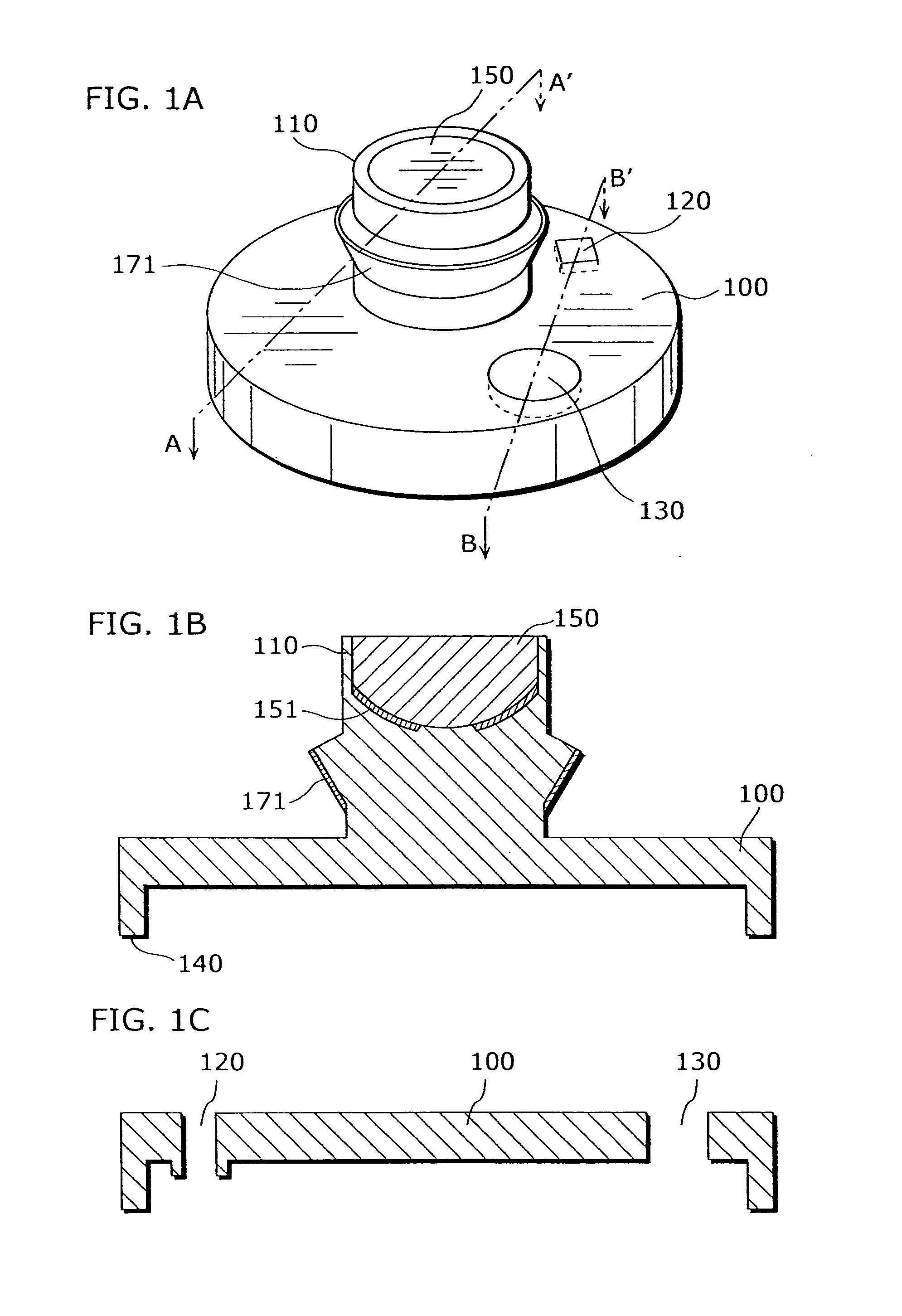
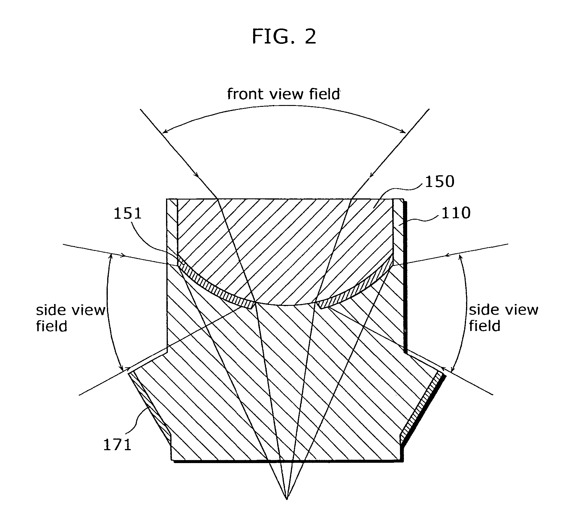
[0041]FIG. 1A is an external view of an endoscope attachment according to the first embodiment. FIGS. 1B and 1C are cross sectional views (taken along lines A-A′ and B-B′ of FIG. 1A) of the endoscope attachment.

[0042]The endoscope attachment according to the first embodiment, which is made of transparent material such as glass or acrylic, is attachable to a probe of an endoscope. The endoscope attachment has: a flat-plate-shaped attaching part 100 which is arranged to cover the distal end of the probe in order to attach the endoscope attachment to the probe; a cylindrical image capturing part 110 which is used to enable a camera in the probe to capture images, and formed on a surface of the attaching part 100 which is the opposite side of the surface contact with the distal end of the probe, in other words, on a top surface of the attaching part 100.

[0043]In the attaching part 100, two holes 120 and 130 are formed to pass through the attaching part 100. The hole 120 is a hole for a ...

second embodiment

[0079]FIG. 11A is an external view of a distal end of a probe of an endoscope to which an endoscope attachment according to the second embodiment is attached. FIGS. 11B and 11C are cross sectional views (taken along lines A-A′ and B-B′ of FIG. 11A) of the distal end of the probe of the endoscope to which the endoscope attachment is attached.

[0080]The endoscope attachment according to the second embodiment has: the flat-plate-shaped attaching part 100; and an image capturing part 1200 which is used to enable the camera of the probe to capture images, and formed on a surface of the attaching part 100 which is the opposite side of the surface contact with the distal end of the probe, in other words, on a top surface of the attaching part 100.

[0081]The image capturing part 1200 has: three (for example) support bars 1220 arranged along the outer periphery of the attaching part 100; and a convex mirror 1210 which has a ring shape and is fixed to the attaching part 100 by the support bars ...

third embodiment

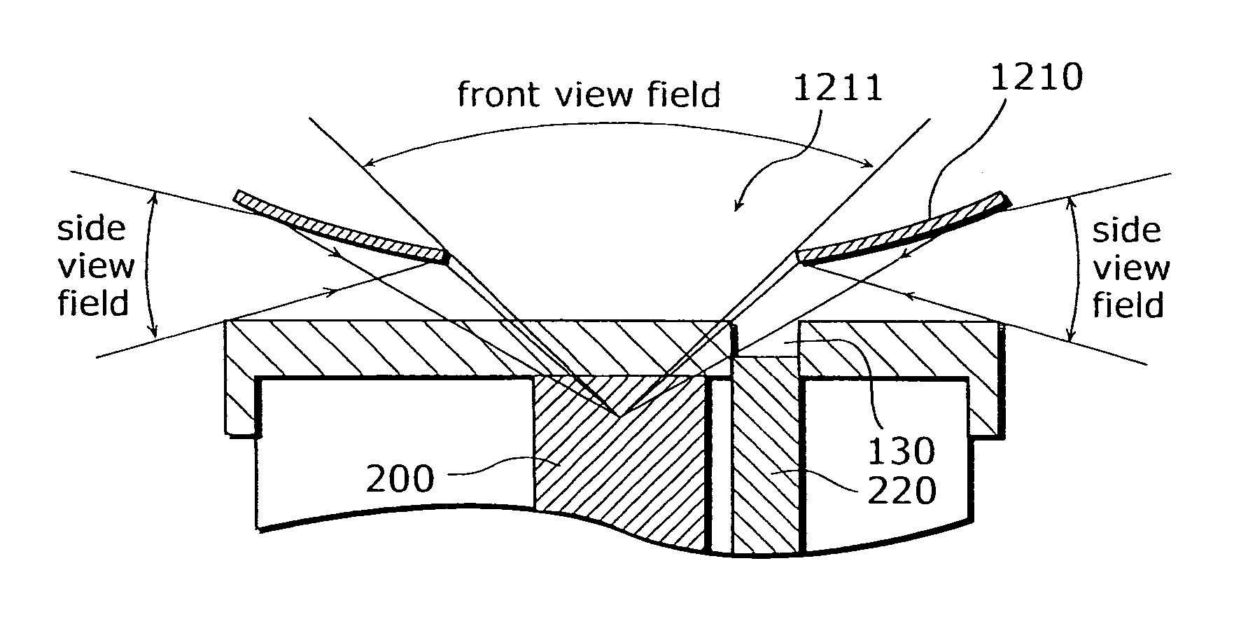
[0090]FIG. 12A is an external view of a distal end of a probe of an endoscope to which the endoscope attachment according to the third embodiment is attached. FIGS. 12B and 12C are cross sectional views (taken along lines A-A′ and B-B′ of FIG. 12A) of the distal end of the probe of the endoscope to which the endoscope attachment.

[0091]The endoscope attachment according to the third embodiment has: the flat-plate-shaped attaching part 100; an image capturing part 1300 which is used to enable the camera of the probe to capture images, and formed on a surface of the attaching part 100 which is the opposite side of the surface contact with the distal end of the probe, in other words, on a top surface of the attaching part 100; and a transparent member 1330 formed on the top surface of the attaching part 100 at a position corresponding to the position of the lighting at the distal end of the endoscope.

[0092]The image capturing part 1300 has: multiple (three, for example) support bars 132...


PUM


Abstract

An endoscope attachment enables an endoscope to capture images of areas in front and at the sides of the endoscope. The endoscope attachment has a transparent attaching part which is used to attach the endoscope attachment to a probe of the endoscope and has two through-holes. A cylindrical transparent image capturing part is used to enable a camera of the probe to capture images and has a trumpet-shaped second mirror on the outer wall of the image capturing part and a wide angle lens with a hyperboloid in the image capturing part. A first mirror is formed at a part of the hyperboloid of the wide angle lens.

Description

BACKGROUND OF THE INVENTION[0001]1. Technical Field[0002]The present invention relates to an endoscope attachment, and more particularly to an endoscope attachment attached to an endoscope used to image the inside of digestive organs, and the endoscope.[0003]2. Background Art[0004]Conventionally, in the field of medical practice, gastrointestinal endoscopes have been used for inspecting digestive organs. The gastrointestinal endoscopes are classified to an upper endoscope used to inspect esophagus, stomach and duodenum, and a lower endoscope used to inspect rectum and large intestine. A probe of the upper endoscope is inserted from an oral cavity, while a probe of the lower endoscope is inserted from an anus. In addition to the inspection of the digestive organs for discovering suspected lesions, the above endoscopes need to cut and collect the discovered lesions to be examined. Therefore, at an end portion of the endoscope (distal end of the endoscope), not only a camera but also a...

Claims


Application Information

Patent Timeline
Patent Type & Authority Patents(United States)
IPC IPC(8): A61B1/06A61B1/04
CPCA61B1/00096A61B1/00181A61B1/00101
Inventor YASUSHI, YAGITOMIO, ECHIGORYUSUKE, SAGAWA
Owner OSAKA UNIV
Why Eureka
Try Eureka