Adjustable wrench with preset stops

a technology of adjustable wrenches and stops, which is applied in the field of adjustable wrenches, can solve the problems of certain suffering of the prior art powered adjustable wrenches and the prior art lack of control of positioning and stopping, and achieve the effect of quick assembly and quick assembly of the power wrench

Active Publication Date: 2005-11-22
PICONE PRODS
View PDF21 Cites 18 Cited by
  • Summary
  • Abstract
  • Description
  • Claims
  • Application Information

AI Technical Summary

Benefits of technology

[0068]The jaw inserts may be fabricated out of compatible materials such as plastic for soft jaws and metals for hard jaws depending on the particular application. Metal inserts that can be magnetized and be used to assist in picking up and holding a magnetic fastener or object. The jaw inserts may be fabricated with smooth non-marring faces, or with rough texture, or with teeth to aid in gripping a fastener or object.
[0069]As illustrated in FIG. 15, the worm gear 34 is rotatably mounted on a stationary shaft. Preferably, the stationary shaft is in the form of a non-threaded steel dowel pin 64, shown in detail in FIG. 14A. The dowel pin 64 is non-rotatably mounted in the head portion 26 of the wrench body member 23, as shown in FIG. 15, to rotatably support some elements of the drive mechanism, such as the worm gear 34 and pulley or sprocket (not shown) engaging the endless belt 48. A fastener plug, preferably in the form of a plastic ratchet fastener 66, shown in detail in FIG. 14B, is used to contain the dowel pin 64 in the wrench head 26. Such an arrangement of the present invention allows quick assembling of the power wrench by simply placing the slip fit dowel pin 64 into a reciprocal hole in the wrench head 26 and by inserting and press fitting the ratchet fastener 66 to secure the dowel pin 64 within the wrench head 26. Thus, the present invention also provides quick and easy process of assembly and disassembly of the power wrench that eliminates the need to machine thread the worm gear shaft, machine thread the wrench head and machine a screw driver slot on the worm gear shaft.

Problems solved by technology

However, the powered adjustable wrenches of the prior art suffer certain drawbacks due to the fact that they rely on a motor torque to open and close its jaws 3, 4 and to stop the moveable jaw 4.
The powered adjustable wrenches of the prior art do not have means to control positioning and stopping of the moveable jaw at predetermined stops for both open and close directions.

Method used


Image

  • Adjustable wrench with preset stops
  • Adjustable wrench with preset stops
  • Adjustable wrench with preset stops

Examples


Embodiment Construction

[0044]The preferred embodiments of the present invention will now be described with the reference to accompanying drawings.

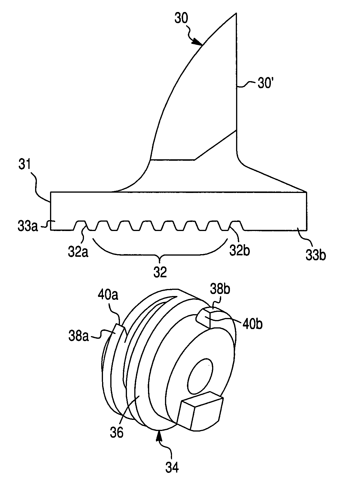
[0045]Referring now to FIG. 4, an improved powered adjustable wrench according to the preferred embodiment of the present invention is illustrated generally at 21 and comprises a wrench body 22 including a wrench body member 23 provided with a stationary jaw 28, and a handle cover 29 removably fastened to the wrench body member 23, and a movable jaw 30 adjustable relative to the stationary jaw 28. As illustrated in FIG. 5, the stationary jaw 28 has a jaw surface 28′, while the movable jaw 30 has a jaw surface 30′, as shown in FIG. 8.

[0046]The wrench body member 23 includes a handle portion 24 and a head portion 26. The stationary jaw 28 is integral to the head portion 26. Preferably, the handle portion 24 and the head portion 26 of the wrench body member 23, illustrated further in detail in FIG. 5, form a unitary single-piece part. It will be appreciated by thos...


PUM


Abstract

An adjustable wrench comprising a moveable jaw, a stationary jaw, and a worm gear driving the moveable jaw. The worm gear is, in turn, meshed with a rack of the moveable jaw and is driven by a reversible servomotor. Activation of the servomotor produces linear reciprocating motion of the moveable jaw. The adjustable wrench further includes a positioning device provided for limiting a travel of the moveable jaw in at least one direction away from or toward the stationary jaw. Preferably, the positioning device includes a first preset stop for limiting a travel of the moveable jaw in the direction toward the stationary jaw to define an inward limit of travel of the moveable jaw and a second preset stop for limiting a travel of the moveable jaw the directions away from the stationary jaw to define an outward limit of travel of the moveable jaw.

Description

CROSS-REFERENCE TO RELATED APPLICATION[0001]This Application claims the benefit under 35 U.S.C. 119(e) of U.S. Provisional Application No. 60 / 442,536 filed Jan. 27, 2003 by John A. Picone.BACKGROUND OF THE INVENTION[0002]1. Field of the Invention[0003]The present invention relates generally to wrenches and, more particularly, to an adjustable wrench having a sliding side jaw.[0004]2. Description of the Prior Art[0005]An powered adjustable wrench having a moveable jaw and a stationary jaw is known in the prior art. As illustrated in FIG. 1A, the powered adjustable wrench 1 of the prior art includes a wrench body having a wrench head 2 formed integrally with the stationary jaw 3 and the moveable jaw 4 adjustable relative to the stationary jaw 3. A worm gear 5 having a pulley 6 is rotated by a belt 7 and a motor pulley 8. The moveable jaw 4 is provided with an integral gear rack for engagement with the worm gear 5. The worm gear 5 is positioned between the fixed jaw 2 and the pulley 6....

Claims


Application Information

Patent Timeline
Patent Type & Authority Patents(United States)
IPC IPC(8): B25B13/00B25B13/14
CPCB25B13/12B25B13/14
Inventor PICONE, JOHN A.
Owner PICONE PRODS
Why Eureka
Try Eureka