Method for controlling an arrangement for supplying electric current to a power supply system

a technology of power supply system and arrangement, applied in the integration of power network operation system, machine/engine, greenhouse gas reduction, etc., can solve the problems of increasing power subject to narrow limits, increasing the complexity of converting the kinetic energy of the rotor, and not being able to solve the problem of increasing the power, so as to avoid unexpected fluctuations, improve the stability of the system, and stabilize the feed

Active Publication Date: 2015-03-12
WOBBEN PROPERTIES GMBH
View PDF1 Cites 21 Cited by
  • Summary
  • Abstract
  • Description
  • Claims
  • Application Information

AI Technical Summary

Benefits of technology

[0025]It is clear that feeding the third proportion of the generated power into the electrical store cannot take place permanently at high power. Preferably, the electrical energy store is controlled or the third proportion of the generated electrical power is adjusted in such a way that the electrical store is always fully charged in order to have as much reserve power available as possible. However, the electrical energy store can also be used to provide its energy not only in exceptional situations but to thereby quite generally react to a fluctuating system demand or compensate for fluctuations in the wind.
[0026]Diverting the second proportion of the power or some of this for feeding in particular provides a quick possible way of reacting to a sudden power demand, or even to have a system-supporting effect in the event of a fault if such a fault event can be counteracted with an increased power feed. This diversion of the second proportion of the power is in particular very quickly possible because the required electrical power is already available as the electrical energy.
[0027]At the same time, diverting this second proportion can also take place variably such that a stabilization of the feed of electrical power into the system takes place. In other words, it is possible to achieve a situation in which a constant power is fed into the electrical system despite fluctuating wind. Stabilization of the feed is thus possible. Even such a stabilization can have an advantageous effect on the system stability because the feed is uniform and, as a consequence of this, unexpected fluctuations can also be avoided. In other words, it is possible to counter misgivings in respect of a problem for the system stability in wind energy installations owing to the fact that there is the theoretical risk that a great number of wind energy installations suddenly, in uncoordinated fashion, feed less power or more power at the same time which, in an extreme case, would result in a collapse of the system. Although these misgivings appear to be ungrounded, depending on the wind energy installations used, or at least do not represent such a considerable problem as is often seen, the proposed stabilization can eliminate such misgivings.
[0028]The use of the electrical store can likewise promote such a stabilization and in addition an increase in the power that can be fed can go beyond the prevailing wind power and therefore in principle also beyond the rated power of the wind energy installation or wind energy installations involved.

Problems solved by technology

Such a system-parallel operating mode is problematic for the system with an increasing share of electrical power from wind energy installations in the system, however.
All of these methods make a contribution to the system support, but do not resolve the fact that a wind energy installation can generate no more electrical power from the wind than the wind conditions prevailing in each case permit.
Such an increase in power is also subject to narrow limits which result not least from the maximum stored kinetic energy in the rotor.
In addition, a certain degree of complexity is required to convert the kinetic energy of the rotor of the wind energy installation into electrical current in order to effect the desired increase in the fed electrical power.

Method used


Image

  • Method for controlling an arrangement for supplying electric current to a power supply system
  • Method for controlling an arrangement for supplying electric current to a power supply system
  • Method for controlling an arrangement for supplying electric current to a power supply system

Examples


Embodiment Construction

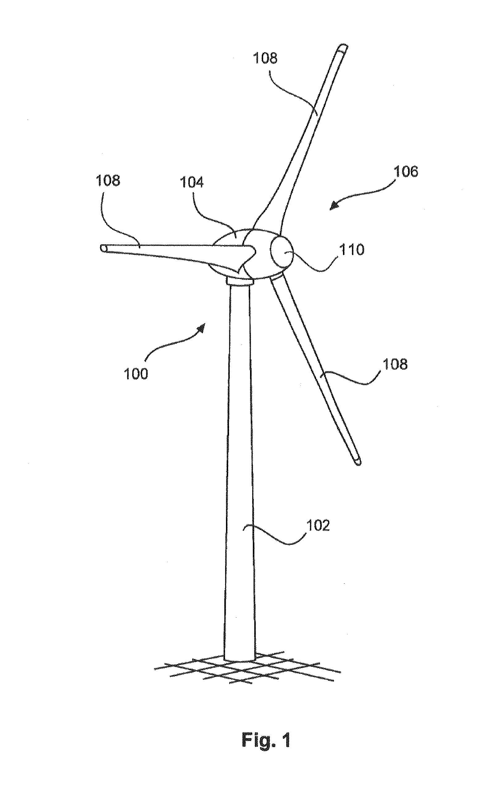
[0052]FIG. 1 shows a wind energy installation 100 with a tower 102 and a pod 104. A rotor 106 with three rotor blades 108 and a spinner 110 is arranged on the pod 104. The rotor 106 is caused to perform a rotary movement during operation owing to the wind and thereby drives a generator in the pod 104.

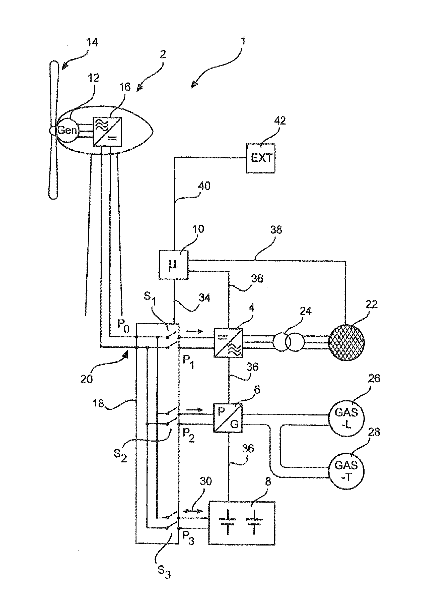
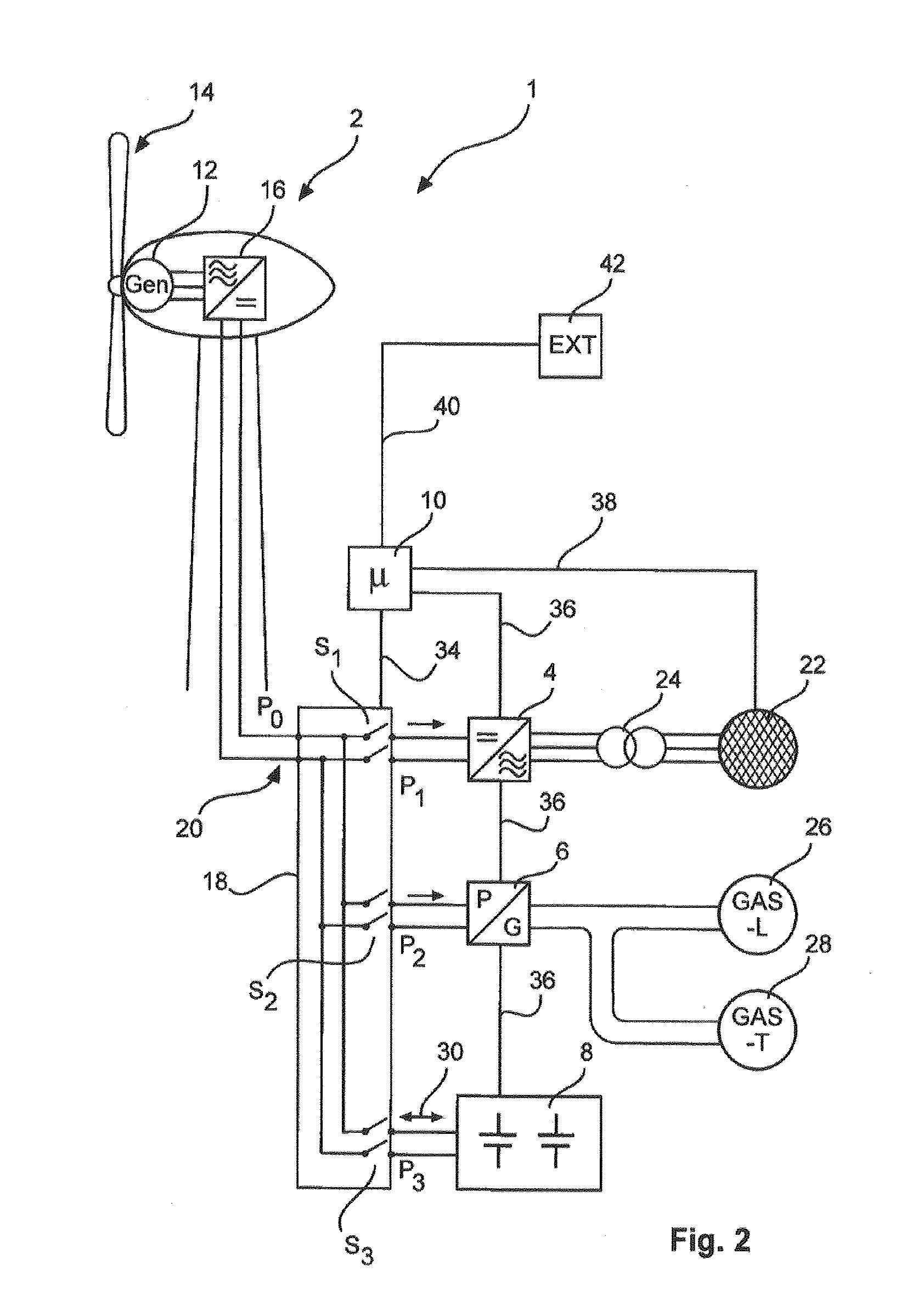
[0053]FIG. 2 shows a feed arrangement 1 with a wind energy installation 2, such as the wind energy installation 100 of FIG. 1, a feed means 4, such as an inverter, an electrical consumer 6, which in one embodiment is a power conversion apparatus 6, an electrical store 8 and a control device 10, which in the illustrated embodiment is a microcontroller 10.

[0054]During operation in accordance with one operating mode, in which there is sufficient wind, the wind energy installation 2 generates an electrical AC voltage by virtue of the generator 12, which is driven by the wind via the aerodynamic rotor 14. This generated AC voltage is supplied to a rectifier 16, which generates a DC voltage f...


PUM


Abstract

The invention relates to a method for controlling a feed arrangement having a wind energy installation for feeding electrical power into an electrical supply system, comprising the following steps: generating electrical power using the wind energy installation from wind, feeding a first proportion of the generated electrical power into the electrical supply system, supplying a second proportion of the generated electrical power to an electrical consumer for consuming the supplied second proportion of the generated electrical power, and wherein, depending on at least one monitored system state and/or depending on the prevailing wind, the second proportion of the generated electrical power which is supplied to the consumer is reduced wholly or partially and the first proportion of the electrical power fed into the electrical supply system is increased correspondingly, and to a corresponding feed arrangement.

Description

BACKGROUND[0001]1. Technical Field[0002]The present invention relates to a method for controlling a feed arrangement having a wind energy installation for feeding electrical power or electrical energy into an electrical supply system. Furthermore, the present invention relates to such a feed arrangement. Furthermore, the present invention relates to a wind farm having a plurality of wind energy installations and at least one feed apparatus.[0003]2. Description of the Related Art[0004]Wind energy installations which generate electrical current from wind and feed this electrical current into an electrical supply system are generally known. An example of such a wind energy installation is illustrated schematically in FIG. 1. Such a wind energy installation can therefore also be interpreted as a feed arrangement, which comprises a wind energy installation.[0005]Conventionally, but at least preferably, wind energy installations are or have been operated in the so-called system-parallel o...

Claims


Application Information

Patent Timeline
Patent Type & Authority Applications(United States)
IPC IPC(8): H02J3/28F03D7/02
CPCF03D7/0284H02J3/28H02J2310/12H02J2300/28H02J3/381H02J3/14Y02E10/72Y02E10/76H02J3/46F24D2200/15Y02B70/3225Y02E70/30Y04S20/222
Inventor BEEKMANN, ALFRED
Owner WOBBEN PROPERTIES GMBH
Why Eureka
Try Eureka