Turbine vane with endwall cooling

a turbine vane and endwall cooling technology, which is applied in the direction of engine fuction, stators, machines/engines, etc., can solve the problems of limited turbine inlet temperature, hot flow ingestion into a section of the turbine, and limited material properties of the turbine parts

Inactive Publication Date: 2012-02-21
FLORIDA TURBINE TECH
View PDF3 Cites 17 Cited by
  • Summary
  • Abstract
  • Description
  • Claims
  • Application Information

AI Technical Summary

Benefits of technology

[0010]It is an object of the present invention to provide for a turbine vane with an interstage gap in which the hot gas ingress into the gap is eliminated.

Problems solved by technology

However, the turbine inlet temperature is limited to the material properties of the turbine parts, such as the first stage guide vanes and rotor blades.
Also, the turbine inlet temperature is limited to an amount of cooling that can be produced on a turbine vane or blade.
Another problem with the turbines is hot flow ingestion into a section of the turbine that is sensitive to the high temperatures such as the rim cavities or interstage gaps.
The leading edge of a turbine vane generates upstream pressure variations which can lead to hot gas ingress into the front gap.

Method used


Image

  • Turbine vane with endwall cooling
  • Turbine vane with endwall cooling

Examples


Embodiment Construction

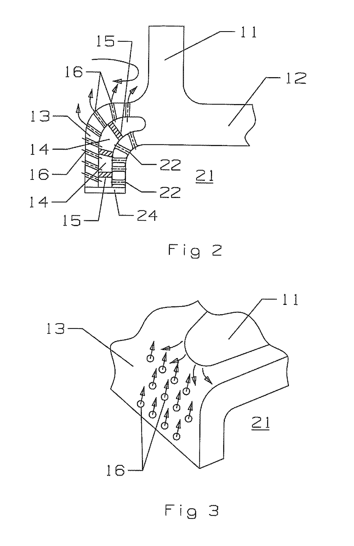
[0019]The present invention is a turbine stator vane for an industrial gas turbine engine. However, the present invention is also usable in an aero engine stator vane as well FIG. 2 shows a cross section side view of a stator vane leading edge endwall with the cooling circuit of the present invention. The stator vane includes a leading edge 11 that extends from an outer endwall (not shown) to an inner endwall 12. The inner endwall 12 extends beyond the leading edge and curves downward to form the flow path for a hot gas flow that is passing through the turbine. This region is referred to as the endwall edge 13.

[0020]The endwall edge 13 includes an outer surface and an inner surface that forms a cooling air supply cavity 21. The endwall edge 13 includes a compartment slot or channel 14 that is machined from the endwall edge 13. A number of compartment divider ribs 15 separate a number of compartments 14 from each other. The inner surface includes a number of impingement holes 22 that...


PUM


Abstract

A turbine stator vane with an outer endwall and an inner endwall, and with an airfoil extending between the two endwalls. The inner endwall includes an endwall edge with a plurality of slots each separated to form compartment slots. A number of impingement cooling holes discharge cooling an from a cooling air supply cavity into the compartment slots to produce impingement cooling for the backside wall of the endwall edge surface. A number of film cooling holes are connected to the compartment slots and discharge the spent impingement cooling an as a layer of film cooling air onto the outer surface of the endwall edge to counter act a bow wave hot gas flow and to provide cooling for the endwall edge to keep a low metal temperature and improve LCF for the vane.

Description

GOVERNMENT LICENSE RIGHTS[0001]None.CROSS-REFERENCE TO RELATED APPLICATIONS[0002]None.BACKGROUND OF THE INVENTION[0003]1. Field of the Invention[0004]The present invention relates generally to a gas turbine engine, and more specifically to a turbine vane.[0005]2. Description of the Related Art including information disclosed under 37 CFR 1.97 and 1.98[0006]A gas turbine engine, such as an industrial gas turbine (IGT) engine, includes a turbine with multiple rows or stages or stator vanes that guide a high temperature gas flow through adjacent rotors of rotor blades to produce mechanical power and drive a bypass fan, in the case of an aero engine, or an electric generator, in the case of an IGT. In both cases, the turbine is also used to drive the compressor.[0007]It is well known that the efficiency of the engine can be increased by passing a higher temperature gas flow into the turbine. However, the turbine inlet temperature is limited to the material properties of the turbine part...

Claims


Application Information

Patent Timeline
Patent Type & Authority Patents(United States)
IPC IPC(8): F01D5/08
CPCF01D9/041F05D2240/121F05D2240/303F05D2240/81F05D2260/201F05D2260/202F05D2260/205
Inventor LIANG, GEORGE
Owner FLORIDA TURBINE TECH
Why Eureka
Try Eureka