Apparatus and method to measure fluid resistivity

a technology of fluid resistivity and apparatus, which is applied in the direction of fluid resistance measurement, instruments, and wellbore/well accessories, etc., can solve the problems of difficult to achieve pressure seals between all of the insulated tubes and metal tubes, unreliable four-way feed-throughs of bulkheads, and the electrical devices are exposed to fluids in the flow lin

Active Publication Date: 2007-02-27
SCHLUMBERGER TECH CORP
View PDF16 Cites 33 Cited by
  • Summary
  • Abstract
  • Description
  • Claims
  • Application Information

AI Technical Summary

Benefits of technology

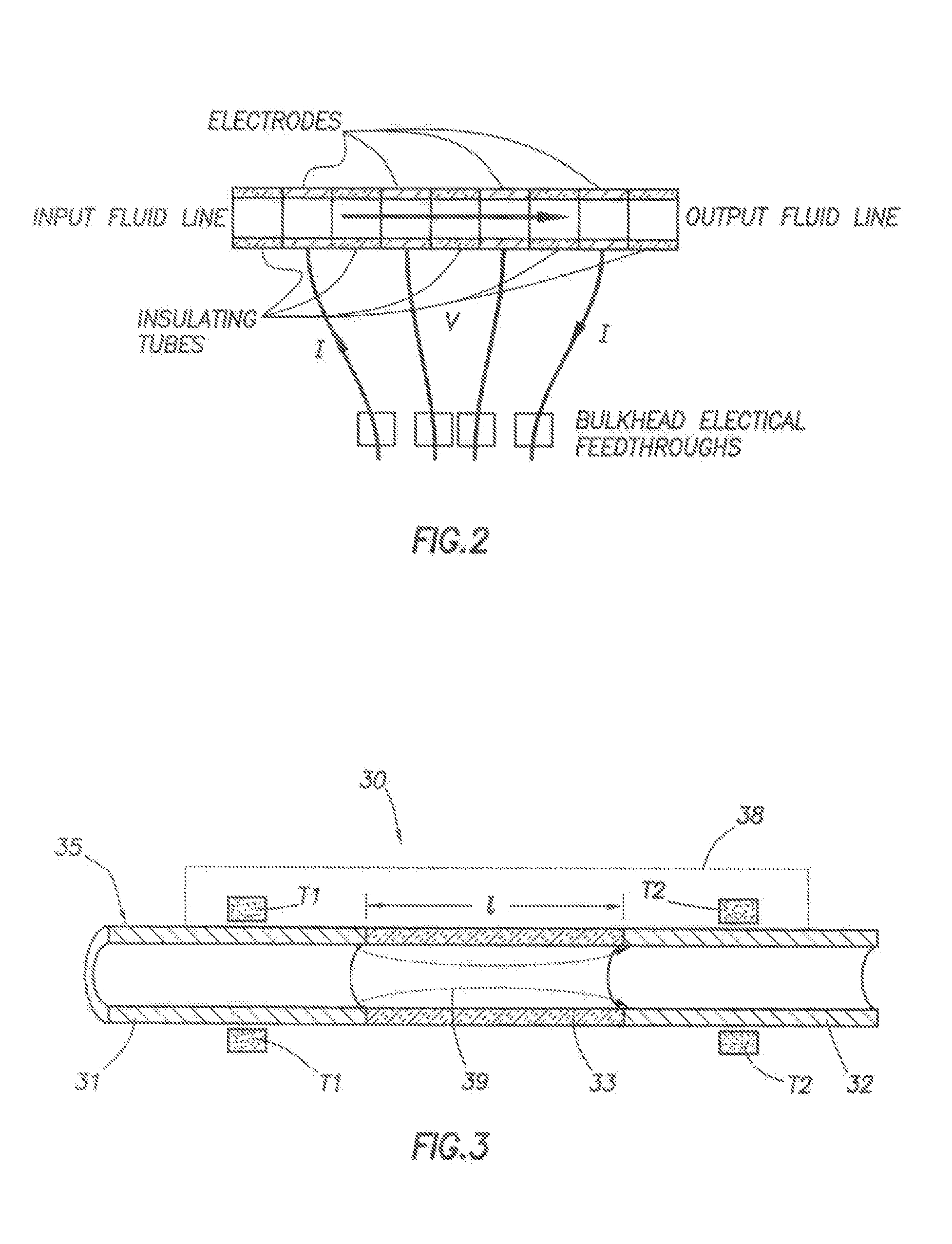
[0012]Another aspect of the invention relates to methods for measuring resistivity of a formation fluid in a borehole. A method in accordance with one embodiment of the invention includes flowing the formation fluid through a flow line of a resistivity measurement apparatus, the flow line including an insulating section between a first conductive section and a second conductive section; inducing an electrical current in the formation fluid in the flow line with a first toroid; and measuring the electrical current induced in the formation fluid with a second toroid.
[0013]Other aspects and advantages of the invention will be apparent from the following description and the appended claims.

Problems solved by technology

However, these electrode devices are exposed to the fluids in the flow line that can be relatively high pressures (up to 30,000 psi).
In the limited volume available for the resistivity sensor, it is difficult to achieve pressure seals between all of the insulated tubes and metal tubes.
At extreme temperatures and pressures, even the four bulkhead feed-throughs can be unreliable.
As a result, there is great difficulty in producing a reliable resistivity sensor.

Method used


Image

  • Apparatus and method to measure fluid resistivity
  • Apparatus and method to measure fluid resistivity
  • Apparatus and method to measure fluid resistivity

Examples


Embodiment Construction

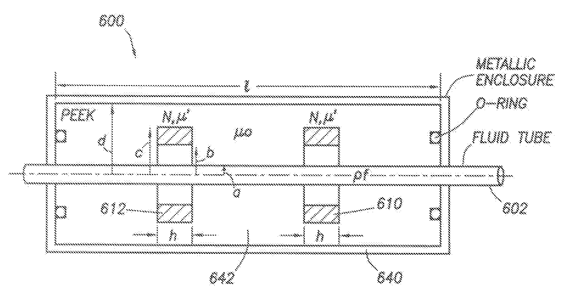
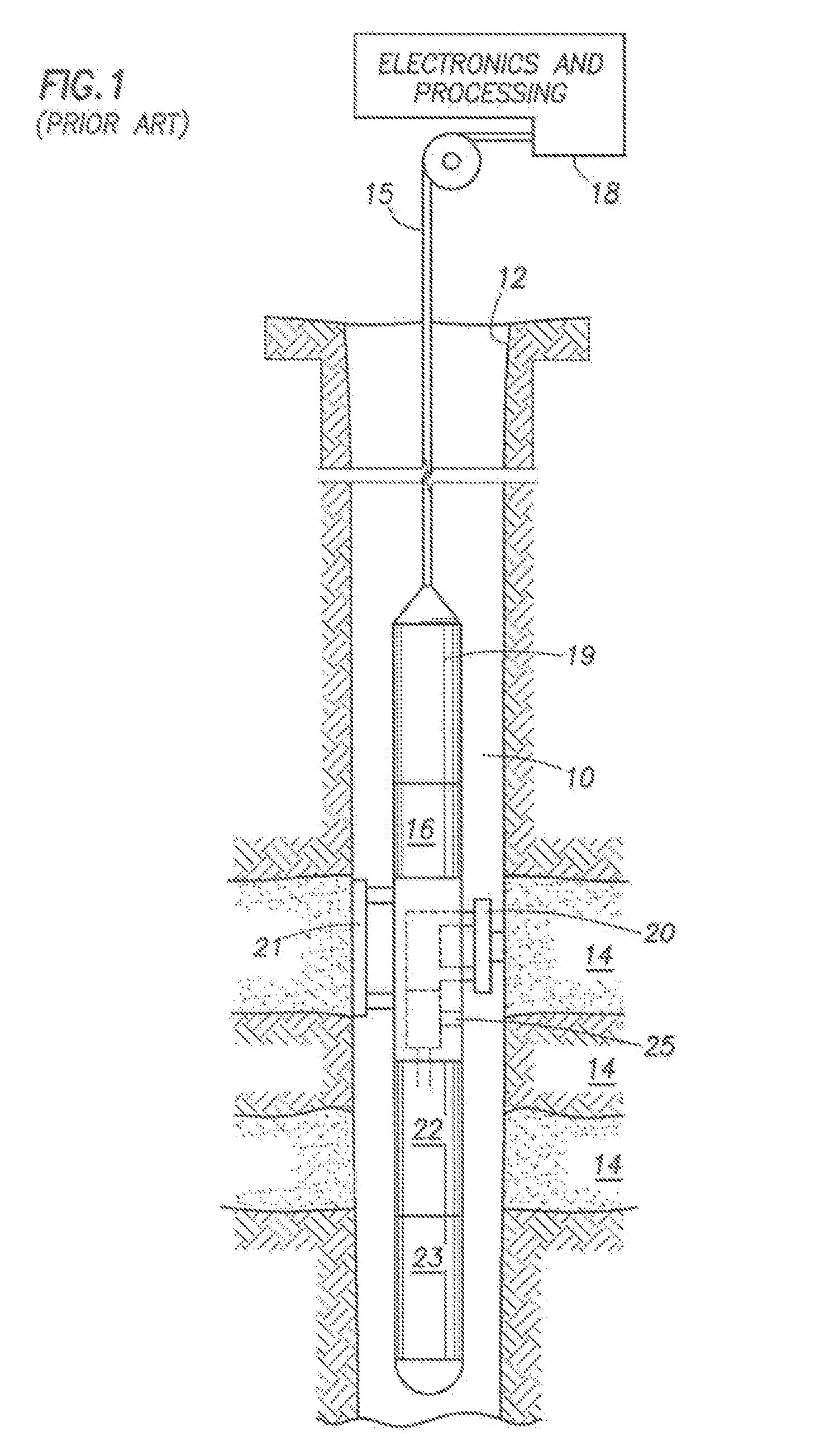
[0028]Embodiments of the invention relate to a resistivity sensor suitable for use in a formation tester or similar equipment. A resistivity sensor in accordance with embodiments of the invention does not rely on electrodes that are in direct contact with the fluids for resistivity measurement. Instead, a resistivity sensor in accordance with embodiments of the invention uses toroids to inductively measure the resistivity of the fluids in a flow line. A resistivity sensor in accordance with embodiments of the invention may be used in a fluid analyzer of a formation tester (e.g., 25 in FIG. 1).

[0029]FIG. 3 shows a schematic of a toroid-based resistivity sensor in accordance with one embodiment of the invention. As shown in FIG. 3, the resistivity sensor 30 includes a flow line 35 that is comprised of an insulating segment 33 flanked by two conductive segments 31, 32. Note that the insulating segment 33 is shown to be made entirely of an electrically insulating material (e.g., ceramic...


PUM


Abstract

An apparatus for measuring fluid resistivity includes a flow line adapted to be in fluid communication with formation fluids, wherein the flow line includes a first section comprising a first conductive area, a second section comprising a second conductive area, and an insulating section disposed between the first section and the second section to prevent direct electrical communication between the first section and the second section; a first toroid and a second toroid surrounding the flow line around the first section and the second section, respectively, wherein the first toroid is configured to induce an electrical current in a fluid in the flow line and the second toroid is configured to measure the electrical current induced in the fluid in the flow line; and an electronic package to control functions of the first toroid and the second toroid.

Description

CROSS-REFERENCE TO RELATED APPLICATIONS[0001]Not applicable.STATEMENT REGARDING FEDERALLY SPONSORED RESEARCH OR DEVELOPMENT[0002]Not applicable.BACKGROUND OF INVENTION[0003]Boreholes are drilled into the Earth's formation to recover deposits of hydrocarbons and other desirable materials trapped in the formations below. Typically, a well is drilled by connecting a drill bit to the lower end of a series of coupled sections of tubular pipe known as a drillstring. Drilling fluids, or mud, are pumped down through a central bore of the drillstring and exit through ports located at the drill bit. The drilling fluids act to lubricate and cool the drill bit, to carry cuttings back to the surface, and to establish sufficient hydrostatic “head” to prevent formation fluids from “blowing out” the borehole once they are reached. When the borehole is drilled deep enough to reach a point of interest, operations to perforate and fracture the subterranean formation are performed to enable hydrocarbon...

Claims


Application Information

Patent Timeline
Patent Type & Authority Patents(United States)
IPC IPC(8): G01R27/08
CPCG01V3/20E21B49/10E21B49/088G01N27/025G01N27/06G01N27/10G01R27/22E21B49/08
Inventor HOMAN, DEAN M.CAO, ANDREW HIEUCLARK, BRIAN
Owner SCHLUMBERGER TECH CORP
Why Eureka
Try Eureka