Low-profile disk unit

a disk unit and low-profile technology, applied in the field of low-profile disk units, can solve the problems of reducing the thickness of the disk unit, difficult to further reduce the clearance between the tray b>3/b> and its cover, and preventing the characteristic of the support structure of the tray, so as to increase the reliability of the disk unit against vibration

Inactive Publication Date: 2007-02-27
TEAC CORP
View PDF1 Cites 10 Cited by
  • Summary
  • Abstract
  • Description
  • Claims
  • Application Information

AI Technical Summary

Benefits of technology

[0031]According to the above-described disk unit, the tray can be supported under substantially the same conditions whether the disk unit is placed in a horizontal or vertical position. Thereby, the vibration characteristic of the support structure of the tray can be prevented from varying depending on the attachment position of the disk unit, so that the reliability of the disk unit against vibration can be increased.

Problems solved by technology

There is a limit, however, to the reduction of the turntable 4, the turntable motor, and the optical pickup 5 in thickness, which makes it difficult to further reduce the disk unit in thickness.
This increases the cumulative value of the dimensional tolerances of the members, thus making it difficult to reduce the clearance between the tray 3 and its cover.
Thereby, the reduction of the disk unit in thickness is also limited.

Method used


Image

  • Low-profile disk unit
  • Low-profile disk unit
  • Low-profile disk unit

Examples


Embodiment Construction

[0049]A description will now be given, with reference to the accompanying drawings, of an embodiment of the present invention.

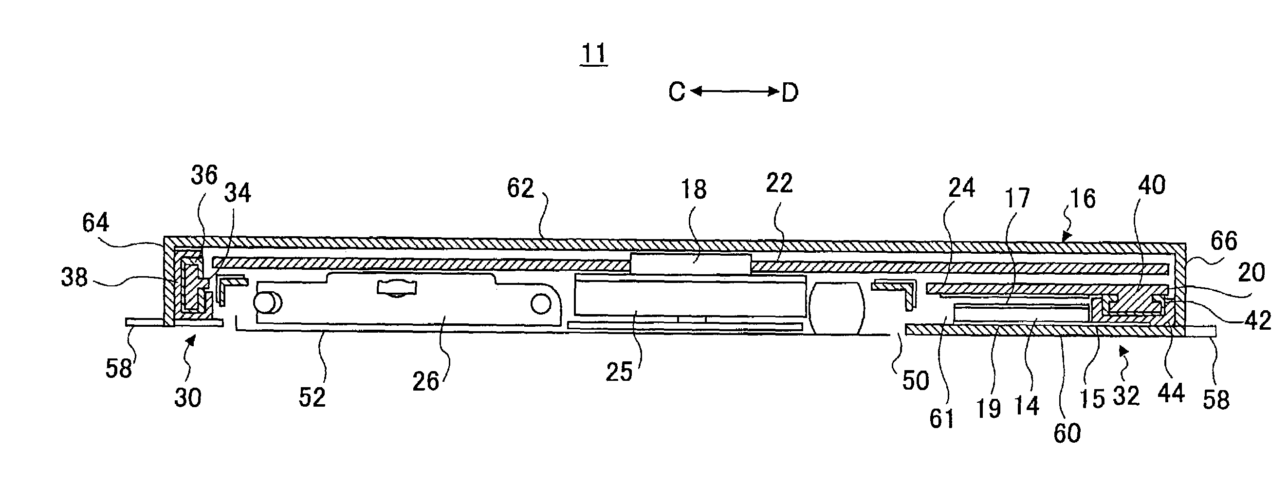
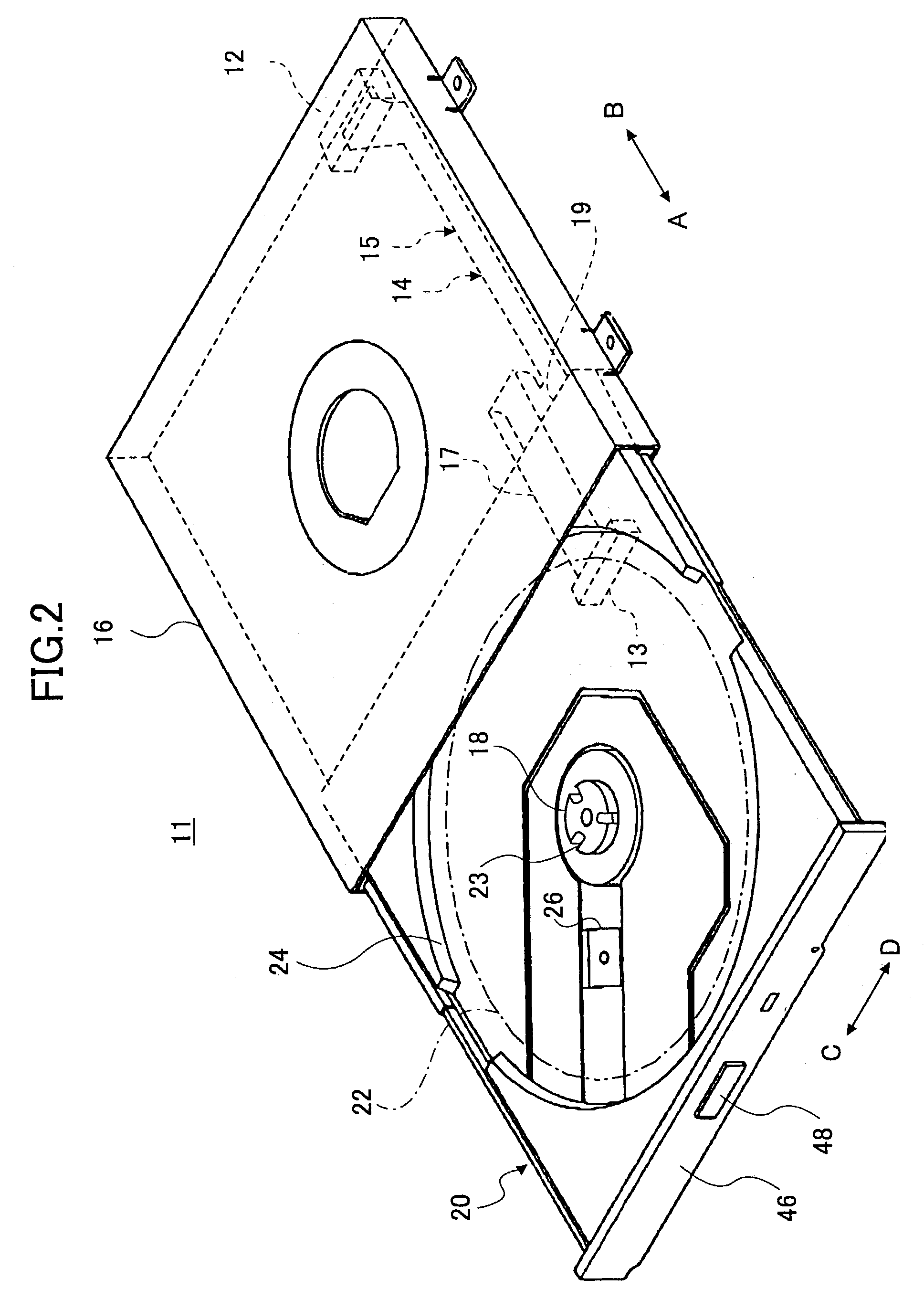
[0050]FIG. 2 is a perspective view of a disk unit 11 according to the embodiment of the present invention. FIG. 3 is a sectional view of the disk unit 11 of FIG. 2 taken along the directions indicated by arrows C and D.

[0051]In FIGS. 2 and 3 and the following drawings, the sides of the disk unit 11 in the directions indicated by arrows A, B, C, and D are referred to as the front side (A side), the rear side (B side), the left side (C side), and the right side (D side), respectively.

[0052]As shown in FIGS. 2 and 3, the disk unit 11 is a drive unit to which a disk-like recording medium such as a CD-ROM, CD-R, CD-RW, DVD-ROM, or DVD-RAM is attached. The disk unit 11 includes a tray 20 supported so as to be slidable inside a shield cover (case) 16. Further, according to the disk unit 11, when an optical disk 22 (indicated by a dot-dash line) is placed on the tray...


PUM

PropertyMeasurementUnit
flexibleaaaaaaaaaa
thicknessaaaaaaaaaa
diameteraaaaaaaaaa

Abstract

A disk unit includes a tray including a turntable to which a disk-like recording medium is attached, a tray guide mechanism supporting the tray so that the tray is movable between a disk-replacing position and a disk-loading position, and a cover formed to cover the disk-like recording medium when the tray is moved to the disk-loading position. The cover comprises a guide support part supporting the tray guide mechanism.

Description

BACKGROUND OF THE INVENTION[0001]1. Field of the Invention[0002]The present invention generally relates to disk units, and more particularly to a disk unit whose tray with a disk-like recording medium attached thereto is movable to a position where data can be recorded on or reproduced from the recording medium.[0003]2. Description of the Related Art[0004]Conventional disk units include CD-ROM units for use in notebook personal computers. In such CD-ROM units, a tray to which a disk-like recording medium (hereinafter referred to simply as a “disk”) is attached is formed to have a width smaller than the diameter of the disk so that the CD-ROM units can be accommodated in personal computers reduced in thickness and weight.[0005]In such CD-ROM units, as shown in FIGS. 1A and 1B, for instance, a tray 3 is supported so as to be slidable in a tray housing 2 of a metal frame 1. A turntable 4 to which a disk 7 is clamped is provided to the upper surface 3a of the tray 3. Further, inside the...

Claims


Application Information

Patent Timeline
Patent Type & Authority Patents(United States)
IPC IPC(8): G11B17/04
CPCG11B17/056G11B17/03
Inventor WATANABE, TAKASHISATO, TAKU
Owner TEAC CORP
Why Eureka
Try Eureka