Tool support device for machine tool

Active Publication Date: 2008-06-17
SUN YING +1
View PDF11 Cites 20 Cited by
  • Summary
  • Abstract
  • Description
  • Claims
  • Application Information

AI Technical Summary

Benefits of technology

[0011]The primary objective of the present invention is to provide a machine tool including an improved tool support device having a compact and shielded configurati

Problems solved by technology

However, a complicated tool carrier and transport means is developed and includes a complicated sprocket-and-chain system for rotating or driving the tool storage rack to rotate relative to the machine base of the machine tools such that the manufacturing cost will be greatly increased, in addition, the complicated sprocket-and-chain system will be exposed and will be easily contaminated and damaged by dirt and cut chips.
However, similarly, the complicated

Method used


Image

  • Tool support device for machine tool
  • Tool support device for machine tool
  • Tool support device for machine tool

Examples


Example

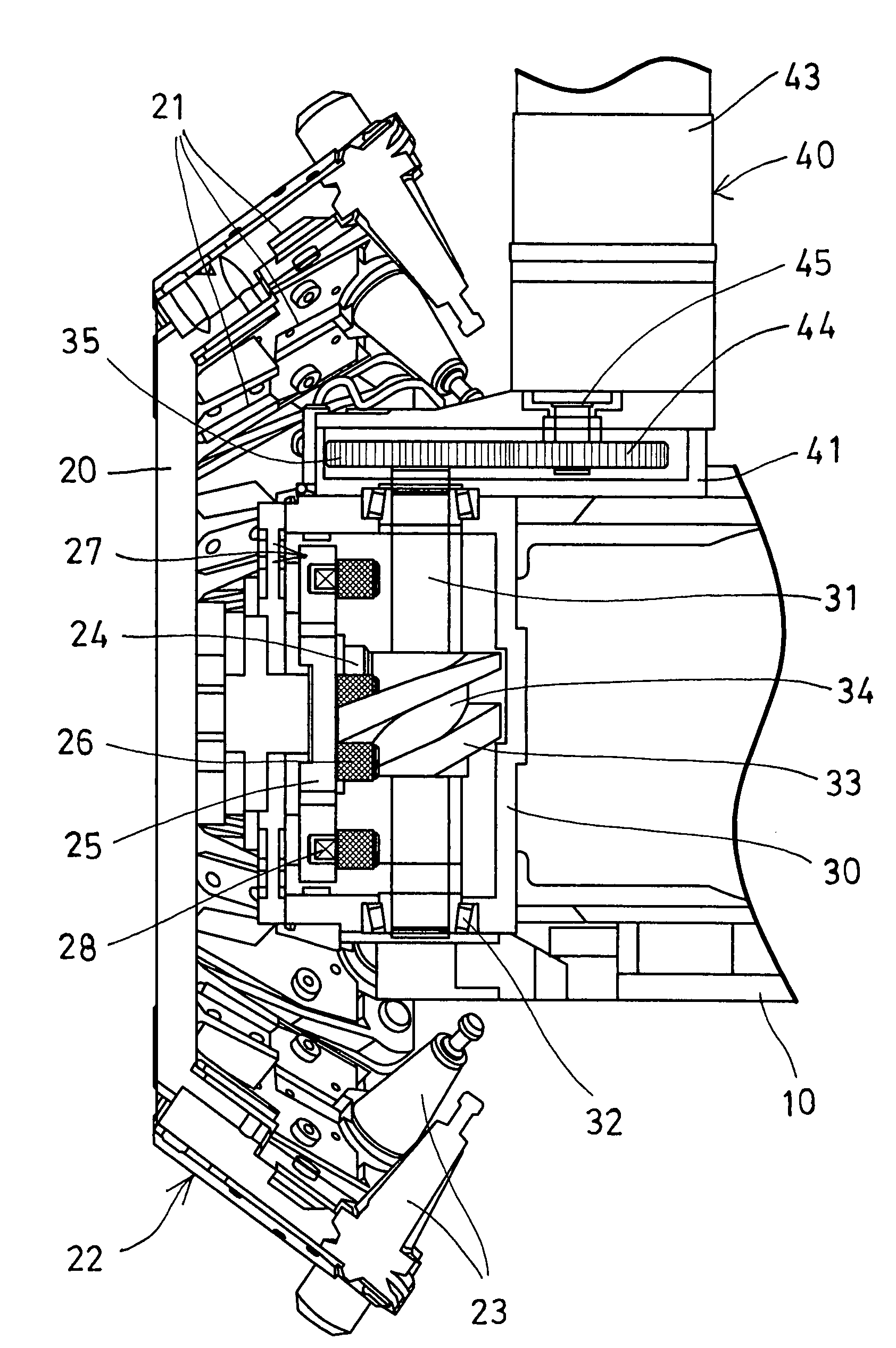
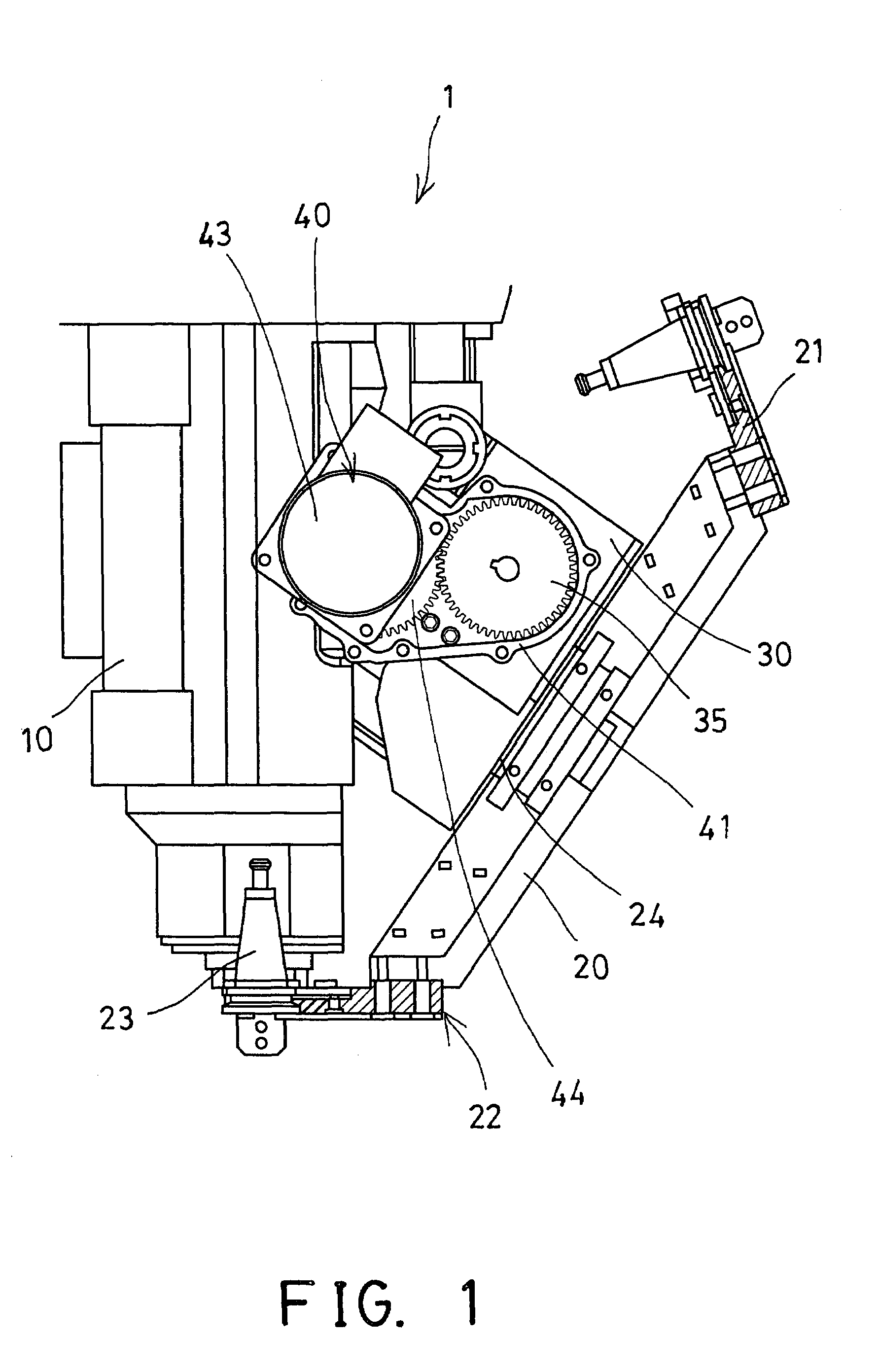
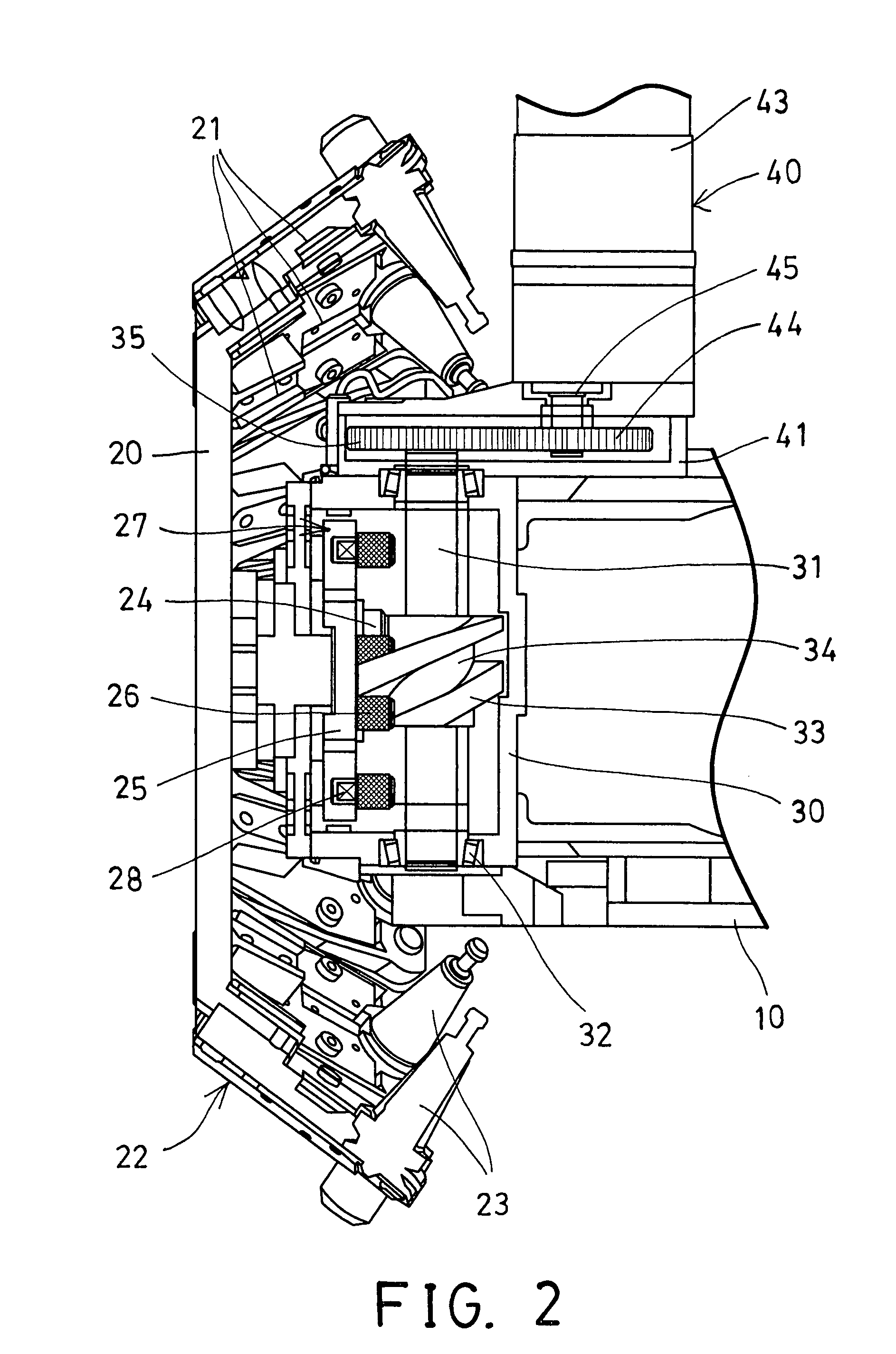
[0020]Referring to the drawings, and initially to FIGS. 1 and 2, a machine tool 1 in accordance with the present invention comprises a tool spindle assembly 10 for attaching and driving selected tool members (not shown), and a disc magazine or tool storage rack 20 rotatably disposed or provided or supported beside the tool spindle assembly 10 and including a number of retainers 21 disposed or provided or supported on the outer peripheral portion 22 of the tool storage rack 20 for attaching or storing and / or retaining tool adapters 23 which may be used for supporting distinct tools members (not shown), and for selectively rotating and sending the tools members toward the tool spindle assembly 10 when the tool storage rack 20 is rotated relative to the tool spindle assembly 10 of the machine tool 1.

[0021]For example, the machine tool 1 includes a receptacle or housing 30 attached or secured to a machine base (not shown) or disposed or provided or supported beside the tool spindle asse...


PUM


Abstract

A tool support device for a machine tool includes a housing disposed beside a tool spindle, a tool storage rack having a shaft rotatably attached to the housing, a plate secured to the shaft and rotatably received in the housing, a number of rollers disposed on the plate, an axle rotatably disposed in the housing and having a rotary member which includes a helical groove for engaging with the rollers and for rotating the plate and the shaft and the tool storage rack relative to the tool spindle, the tool support device includes a compact structure for suitably shielding and protecting the tool support device and for preventing the tool support device from being contaminated and damaged by dirt and cut chips.

Description

BACKGROUND OF THE INVENTION[0001]1. Field of the Invention[0002]The present invention relates to a machine tool, and more particularly to a machine tool including an improved tool support device having a compact and shielded configuration for suitably shielding and protecting the tool support device and for preventing the tool support device from being contaminated and damaged by dirt and cut chips.[0003]2. Description of the Prior Art[0004]Typical machine tools comprise a tool support device having a tool storage rack for supporting various tools or tool adapters at the outer peripheral portion thereof and having a rotating or driving device for rotating the tool storage rack relative to a machine base of the machine tools.[0005]For example, U.S. Pat. No. 4,335,498 to Hague et al. discloses one of the typical machine tools comprising a spindle assembly associated with an indexing tool storage rack on which a number of distinct tools are stored.[0006]However, a complicated tool carr...

Claims


Application Information

Patent Timeline
IPC IPC(8): B23Q3/157
CPCB23Q3/15706Y10T483/1795Y10T483/1755B23Q3/15534
Inventor SUN, YINGSUN, CHI
Owner SUN YING
Why Eureka
Try Eureka