Abrasive belt polishing finisher

a technology of polishing finisher and abrasive belt, which is applied in the field of mechanical technology, can solve the problems of low finishing efficiency, inconvenient operation, and inability to efficiently carry out polishing with flat abrasive belt, and achieve the effect of preventing the connection support and ensuring the reliability of operation

Inactive Publication Date: 2015-12-31
TAIZHOU FEDERAL ROBOT TECH
View PDF5 Cites 22 Cited by
  • Summary
  • Abstract
  • Description
  • Claims
  • Application Information

AI Technical Summary

Benefits of technology

[0030]In the abrasive belt polishing finisher, a positioning cylinder is further fixed within the telescopic piston. Several positioning bores are evenly distributed on the connection support on the same circle using the rotation center thereof as the center of circle. The piston rod of the said positioning cylinder could extend out from the inside of the telescopic piston and insert into the positioning bores. When the telescopic piston is pushed outward to locate the connection support on the back of the abrasive belt, the connection support could be controlled by the rotary motor to rotate until the finishing wheel thereon is pressed against the back of the abrasive belt. In order to guarantee the reliability in operation and prevent the connection support from being collided and influenced, the piston rod of the positioning cylinder within the telescopic piston is controlled to be pushed out and inserted into the positioning bore on the current connection support corresponding to the position of the piston rod of the positioning cylinder, for which the connection support will be held stationary.
[0031]In the abrasive belt polishing finisher, the cylinder body of the said telescopic cylinder has a chute opened from the end to the middle on its side. The side of the telescopic piston is connected with a lug which could slide along the chute. The lug is located within the chute and a portion of the lug extends out of the chute. When the lug is pressed against the end of the chute, the connection support is located at the back of the abrasive belt. Air is supplied to the cylinder body of the telescopic cylinder from an air supply. The telescopic piston within the cylinder body is pushed out under the force of the air pressure. The lug connected with the side of the telescopic piston will move along the chute on the side of the cylinder body. When the lug is moved and pressed against the end of the chute, the connection support is exactly located on the inner side of the abrasive belt, which not only ensures the connection support will be accurately pushed to a designated position, but also achieves the position restricting effect to ensure the telescopic piston will not fall off from the cylinder body.
[0032]In the abrasive belt polishing finisher, a housing is fixed on the side of the frame opposite to the connection support. The driving mechanism has a spin motor fixed on the end of the housing. A via hole is provided on the side of the frame corresponding to the connection support. A positioning sleeve having an inner cavity is threaded with the via hole. The positioning sleeve is located within the housing and the output shaft of the spin motor is connected with one end of the positioning sleeve. The rotary motor is provided within the positioning sleeve. The output shaft of the rotary motor extends out from the other end of the positioning sleeve and is connected with the connection support. The output shaft of the spin motor is controlled to rotate forward. As the output shaft of the spin motor is linked with the positioning cylinder and the positioning cylinder is threaded with the via hole, the forward rotation of the output shaft of the spin motor will bring the positioning cylinder to extend out from the inside of the housing along the threaded section, and lead the connection support to be on the inner side of the abrasive belt. Thereafter, the output shaft of the rotary motor is controlled to drive the connection support into rotation, so that the finishing wheel on the connection support is pressed against the inner side of the abrasive belt. When the connection support does not have to be used or the deformation of the manipulator is hindered by the connection support, the positioning sleeve could be retracted into the housing merely by controlling the output shaft of the spin motor to rotate anticlockwise.

Problems solved by technology

When the conventional abrasive belt polishing finishers are used to finish the work pieces, finishing could not be efficiently carried out by using the flat abrasive belt.
If other finishing wheels have to be removed or replaced, not only is the operation inconvenient, but also the finishing efficiency is low.

Method used


Image

  • Abrasive belt polishing finisher
  • Abrasive belt polishing finisher
  • Abrasive belt polishing finisher

Examples


first embodiment

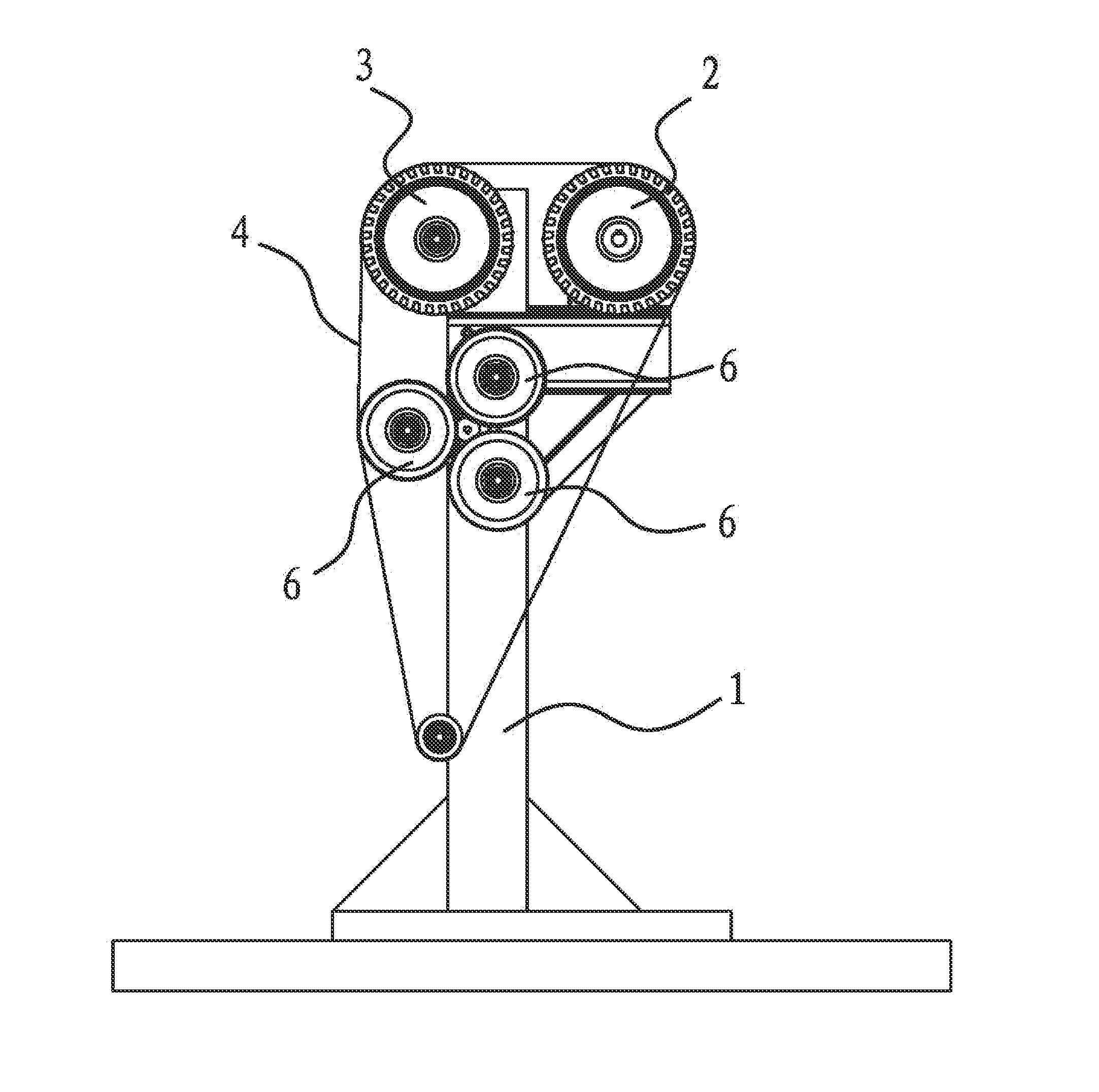
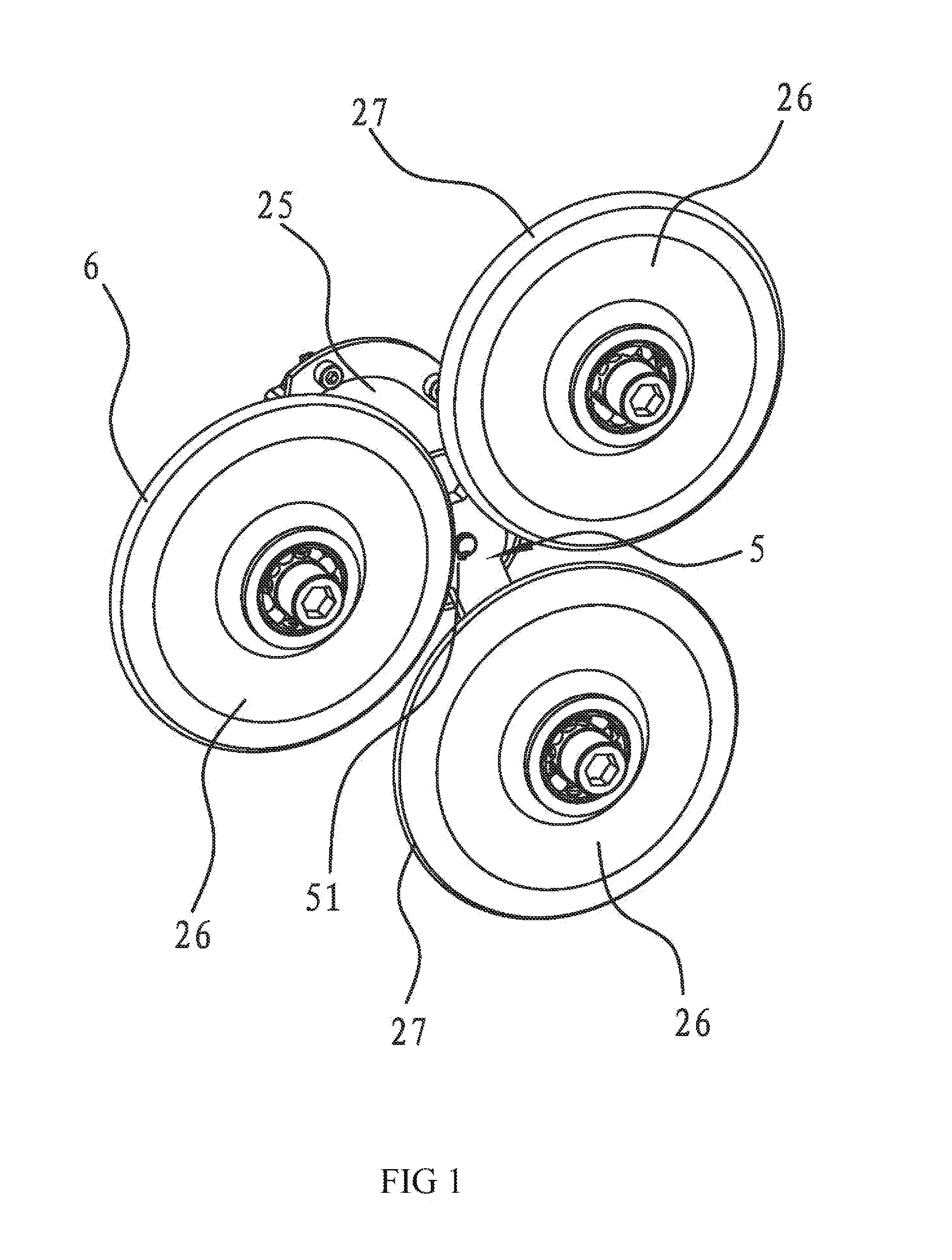
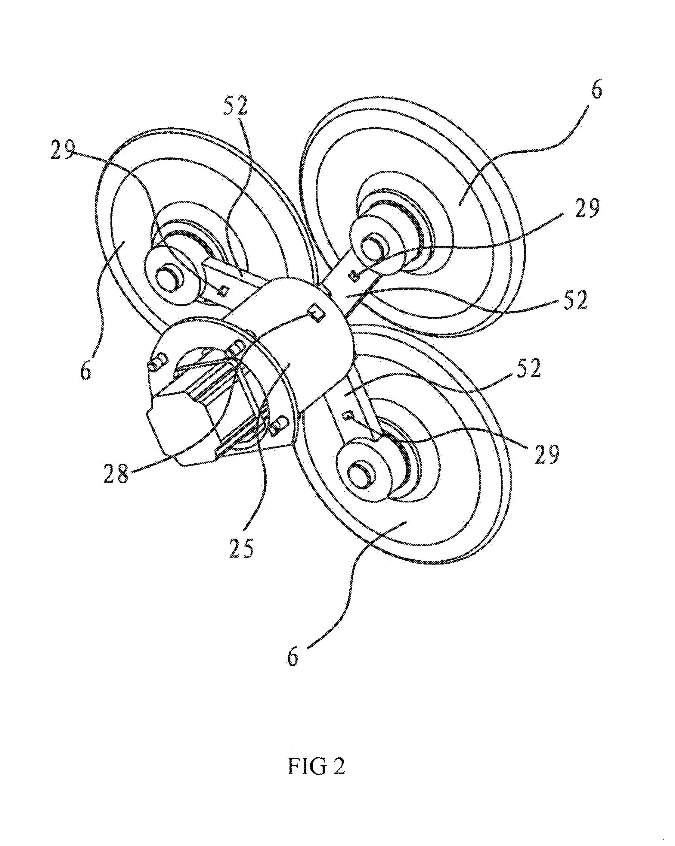
[0055]As shown in FIGS. 1, 2 and 4, the abrasive belt polishing finisher of the invention comprises a frame 1, a driving wheel 2 and a driven wheel 3 provided on the frame 1, and an abrasive belt 4 covered on the driving wheel 2 and the driven wheel 3. The finishing wheel transform mechanism on the frame 1 includes a motor 25, a connection support 5 fixedly connected with the output shaft of the motor 25 at the central section, and three support finishing wheels 6 connected around the connection support 5. The number of the support finishing wheels 6 could be 2, 4, 5 or more as required. The connection support 5 includes an annular connection part 51 and rod-like support parts 52 in the same number as that of the support finishing wheels 6. The connection part 51 is covered outside of and fixedly connected with the output shaft of the motor 25. The inners end of the support parts 52 are integrated with the outer side of the connection part 51, and the other ends thereof are respecti...

second embodiment

[0062]The second embodiment is substantially the same as the first embodiment except the positioning of the detection module and the connection support. The detection modules includes infrared receiving units fixedly connected with the outer side of the motor 25 and infrared emitting units in the same number as that of the support finishing wheels 6. The infrared emitting units are corresponding to the three support parts 52 respectively and move to the positions corresponding to the infrared receiving units when they rotate to the back of the abrasive belt 5 along with the connection support 5. Here, in order to set aside the reaction time for control, the detection position could be put ahead by some distance, and the specific distance could be determined as required. Alternatively, a servo motor or stepper motor for precise control of the positioning operation could be used. The rotation angle could be precisely positioned by the controller to control the precise positioning of t...

third embodiment

[0063]As shown in FIGS. 6, 8 and 10, the abrasive belt polishing finisher refers to an improvement to the finisher according to the first embodiment. The abrasive belt polishing finisher comprises a frame 1 and a driving wheel 2 and driven wheels 3 provided on the frame 1, and an abrasive belt 4 covered on the driving wheel 2 and the driven wheels 3. A driving mechanism connected with the finishing wheel transform mechanism of the first embodiment is further provided on the frame 1. The connection support 5 in the finishing wheel transform mechanism could move between a first position and a second position along the axis of the support finishing wheels 6. In the first position, the driving mechanism drives the connection support 5 in movement to disengage the support finishing wheels 6 from the abrasive belt and locate the support finishing wheels out of an area surrounded by the abrasive belt. In the second position, the driving mechanism drives the connection support to move into ...


PUM


Abstract

The invention discloses an abrasive belt polishing finisher in the field of mechanical technology, which addresses inconvenient operation of the existing polishing finishers. The abrasive belt polishing finisher includes a motor and a connection support. The central section of the connection support is fixedly connected with the output shaft of the motor. Several self-rotable connection support finishing wheels are provided around the connection support. The curve surface of the rim of each of the support finishing wheels has a different curvature. Each connection support finishing wheel is distributed on the same circle centered on the output shaft of the motor. The connection support is driven by the motor into rotation to press and position one of the connection support finishing wheels against the back of the abrasive belt in the polishing finisher. The abrasive belt polishing finisher could satisfy continuous polishing treatment for different curved surfaces.

Description

BACKGROUND OF THE INVENTION[0001]1. Field of Invention[0002]The present invention pertains to the field of mechanical technology. The invention relates to an abrasive belt polishing finisher.[0003]2. Related Art[0004]The polishing finisher is a device particularly designed for finishing the surface of metallic products including steel, aluminum or copper or pipes. By using the polishing finisher, snow patters, drawing patterns, wave patterns, matter surfaces and mirror surfaces of different precisions could be produced, and deep scratches and slight scratches can be quickly repaired. The polishing finisher could be used for deburring and rounding and processing decorative metals, which will not result in any shadow, transition areas or uneven decorative surfaces during processing. As such, the polishing finisher is an important device for production of metallic products.[0005]The abrasive belt polishing finisher grinds the surface of a work piece by means of the driving abrasive bel...

Claims


Application Information

Patent Timeline
Patent Type & Authority Applications(United States)
IPC IPC(8): B24B21/16B24B21/02
CPCB24B21/16B24B21/02B24B21/008B24B21/002B24B21/20
Inventor CHEN, QIYUE
Owner TAIZHOU FEDERAL ROBOT TECH
Why Eureka
Try Eureka