Maximum torque current ratio control method for position-sensorless permanent magnet synchronous motor

A permanent magnet synchronous motor, maximum torque current technology, applied in motor control, motor generator control, electronic commutation motor control, etc., can solve the problems of increased torque fluctuation, motor loss, and signal interference

Active Publication Date: 2019-07-30
TIANJIN UNIV
View PDF5 Cites 12 Cited by
  • Summary
  • Abstract
  • Description
  • Claims
  • Application Information

AI Technical Summary

Problems solved by technology

However, when these two control methods are implemented at the same time, different signals injected into each other will interfere with each other, and further increase torque fluctuation and motor loss

Method used


Image

  • Maximum torque current ratio control method for position-sensorless permanent magnet synchronous motor
  • Maximum torque current ratio control method for position-sensorless permanent magnet synchronous motor
  • Maximum torque current ratio control method for position-sensorless permanent magnet synchronous motor

Examples


Embodiment Construction

[0025] The present invention will be described in further detail below in conjunction with the accompanying drawings and specific embodiments. It should be understood that the specific embodiments described here are only used to explain the present invention, not to limit the present invention.

[0026] Combine below Figure 1-Figure 5 1. The specific calculation formula further introduces the scheme in Embodiment 1, see the following description for details:

[0027] 1. Estimation of rotor position

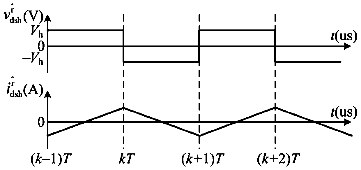
[0028] When the interior permanent magnet synchronous motor operates at low speed, the back EMF and stator resistance voltage drop can be ignored. Under the premise of ensuring that the sampling interval is short enough, in the two-phase rotating coordinate system, the high-frequency model of the motor can be expressed as

[0029]

[0030] In the formula, "r" represents the two-phase rotating coordinate system; "s" represents the stator; "h" represents the high-frequency co...


PUM


Abstract

The invention discloses a maximum torque current ratio control method for a position-sensorless permanent magnet synchronous motor. Based on high frequency square wave voltage injection, a high frequency square wave voltage signal is injected, and the built-in permanent magnet synchronous motor position-sensorless control and maximum torque current ratio control are achieved simultaneously, including two aspects: using the corresponding relationship between the high frequency square wave voltage and the high frequency response current to detect the convex polarity of the built-in permanent magnet synchronous motor, thereby obtaining rotor position information; decomposing the high frequency response current into a component parallel to a current vector angle and a component perpendicular to the current vector angle; and eliminating the component parallel to the current vector angle in the high frequency response current, and using the torque ripple generated by the component perpendicular to the current vector angle to realize tracking of the maximum torque current ratio operating point.

Description

technical field [0001] The invention belongs to the field of built-in permanent magnet synchronous motor control, in particular to a maximum torque-current ratio control method for a position sensorless built-in permanent magnet synchronous motor based on high-frequency square wave injection. Background technique [0002] Due to its high power density, built-in permanent magnet synchronous motors have been widely used in applications such as electric vehicles, household appliances, and rail transit. [0003] Accurate rotor position information is required to achieve high-performance control of built-in permanent magnet synchronous motors. Installing a mechanical rotor position sensor on the motor shaft is an effective way to obtain accurate rotor position information. Commonly used mechanical rotor position sensors include photoelectric encoders, resolvers, etc. However, the installation of the mechanical position sensor will increase the cost of the motor system, increase ...

Claims


Application Information

Patent Timeline
Patent Type & Authority Applications(China)
IPC IPC(8): H02P21/24H02P21/18
CPCH02P2207/05H02P21/18H02P21/24
Inventor 夏长亮林治臣周湛清李新旻史婷娜
Owner TIANJIN UNIV
Why Eureka
Try Eureka