Color-changing illumination device

a technology of illumination device and led light source, which is applied in the direction of semiconductor devices for light sources, point-like light sources, lighting and heating apparatus, etc., can solve the problem of limited visible color spectrum of illumination device incorporating led light sources

Inactive Publication Date: 2007-03-06
ILIGHT TECH INC
View PDF12 Cites 98 Cited by
  • Summary
  • Abstract
  • Description
  • Claims
  • Application Information

AI Technical Summary

Problems solved by technology

However, the available visible color spectrum of an illumination device incorporating LEDs as the light source is limited by the finite availability of LED colors.

Method used


Image

  • Color-changing illumination device
  • Color-changing illumination device
  • Color-changing illumination device

Examples


Embodiment Construction

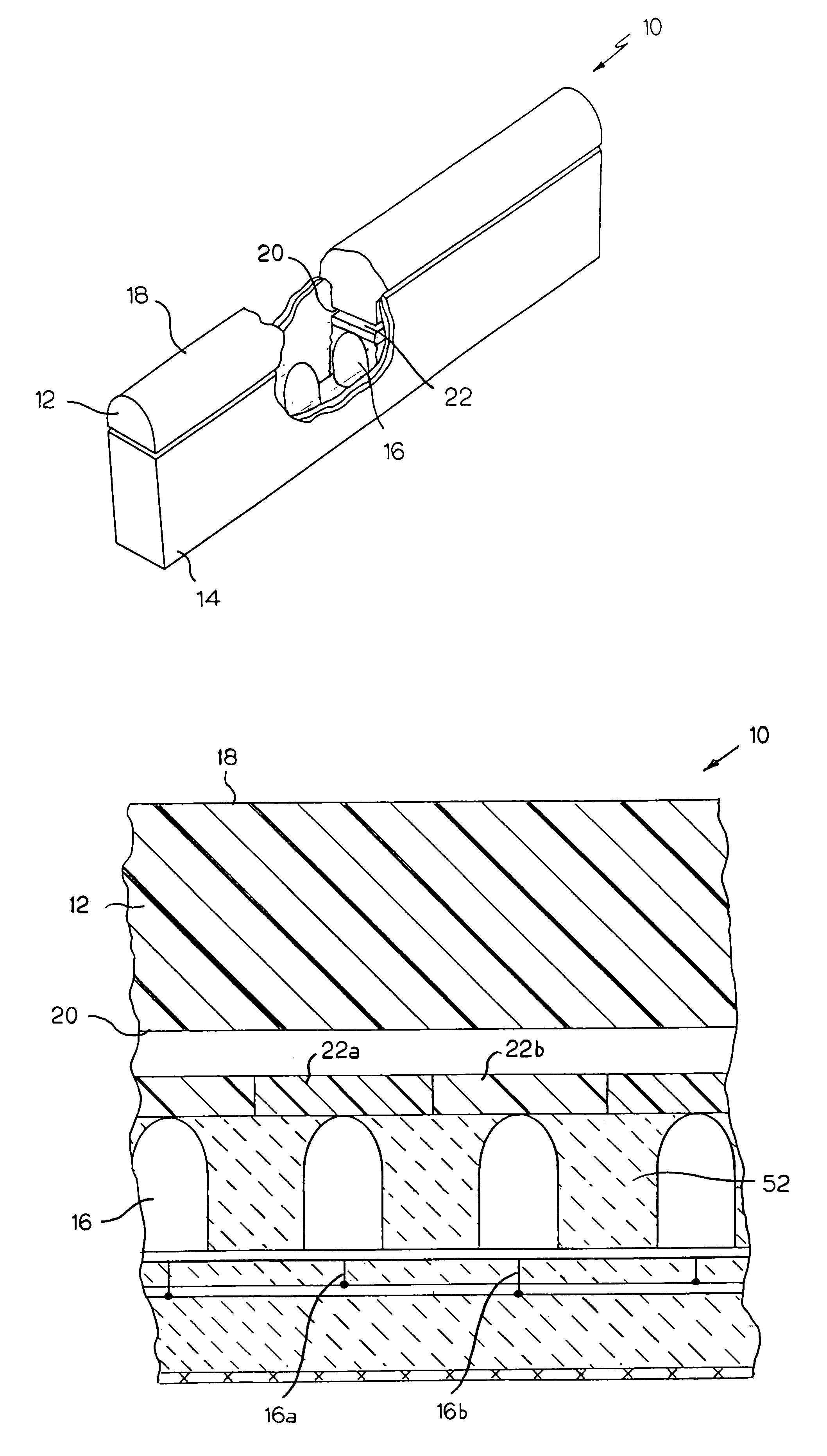
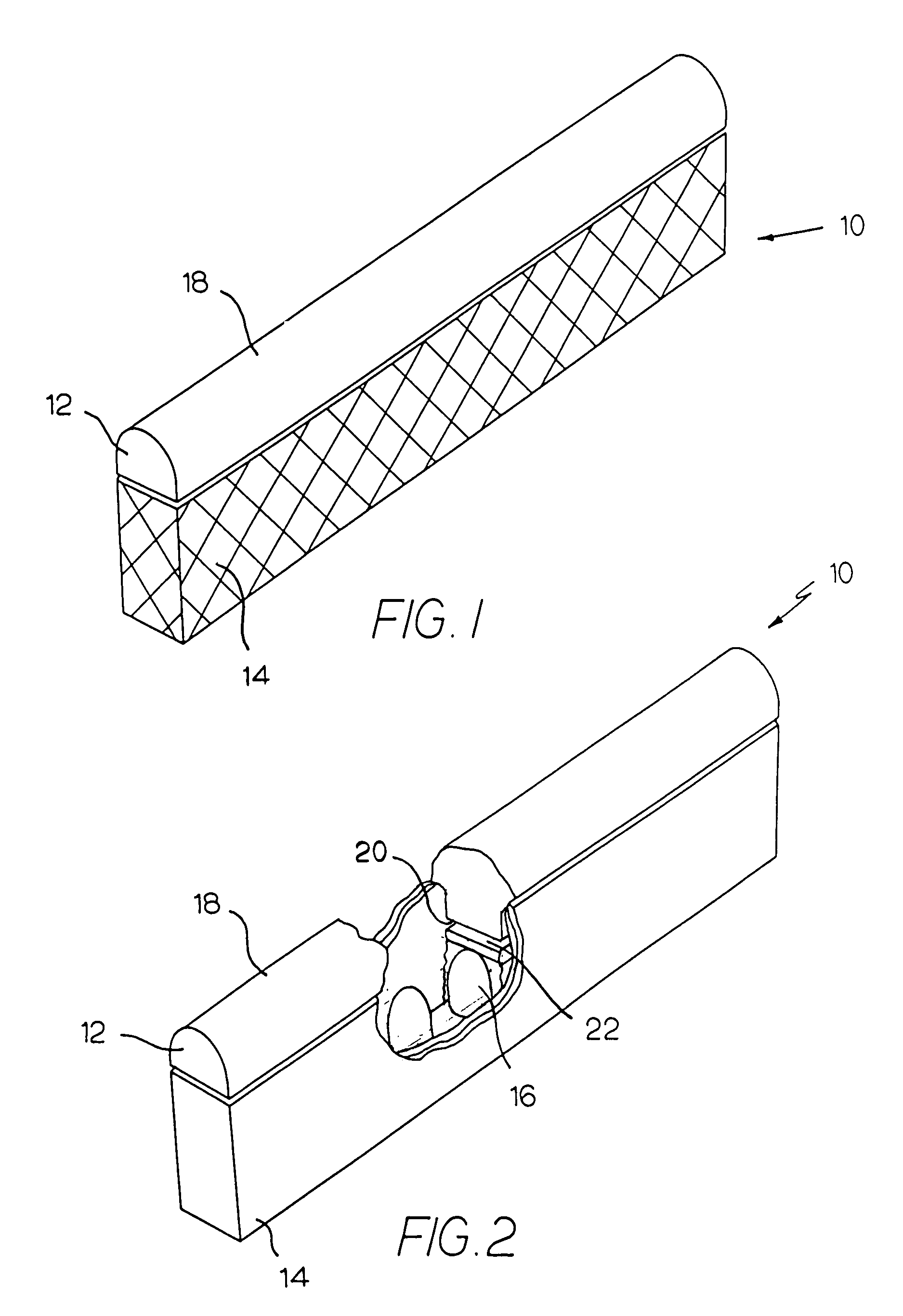
[0023]The present invention is an illumination device for simulating neon or similar lighting, an illumination device that uses one or more fluorescent and / or phosphorescent dyes to provide for emission of light in colors that cannot ordinarily be achieved by the use of LEDs alone, including the ability to control and change the color of the emitted light.

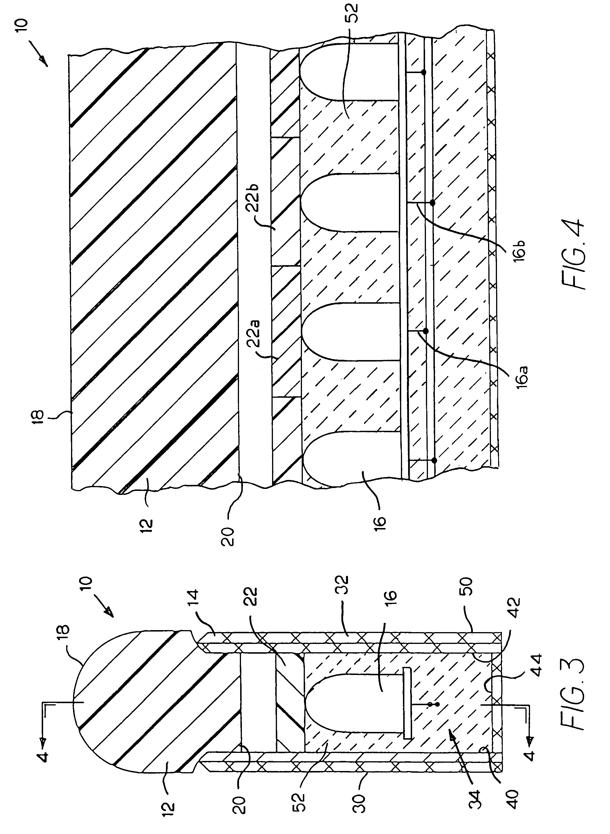
[0024]An exemplary illumination device 10 made in accordance with the present invention is illustrated in FIGS. 1–4. The illumination device 10 is generally comprised of a rod-like member 12, a housing 14, and a light source 16. In this exemplary embodiment, the rod-like member is a “leaky” waveguide 12 that has an external curved lateral surface 18 serving as a light-emitting surface and an interior lateral surface 20 that serves as a light-receiving surface. The characteristics of this waveguide 12 will be further described below, but in general, light entering the waveguide 12 from the light source 16 positioned below the light-...


PUM


Abstract

An illumination device for simulating neon or similar lighting is generally comprised of a rod-like member, a housing, a light source, and an intermediate light-transmitting medium extending along and positioned adjacent the light source with a light-receiving surface for receiving light emitted from said light source and a light-emitting surface for emitting light into the rod-like member. This intermediate light-transmitting medium is preferably composed of a matrix of a substantially translucent acrylic, polyurethane, or similar material tinted with a predetermined combination of one or more fluorescent and / or phosphorescent dyes. The intermediate light-transmitting medium is subdivided into independent sections, each of which is provided with differing combinations of fluorescent dye, phosphorescent dye, and / or no dye at all.

Description

CROSS-REFERENCE TO RELATED APPLICATIONS[0001]The present application is a continuation-in-part of U.S. patent application Ser. No. 11 / 025,019 filed Dec. 29, 2004 and is a continuation-in-part of U.S. patent application Ser. No. 10 / 455,639 filed Jun. 05, 2003 now U.S. Pat. No. 7,011,421, the latter of which is itself a continuation-in-part of U.S. patent application Ser. No. 09 / 982,705, filed on Oct. 18, 2001, now U.S. Pat. No. 6,592,238, the entire disclosures of which are incorporated herein by reference.BACKGROUND OF THE INVENTION[0002]The present invention relates to an illumination device for simulating neon or similar lighting, an illumination device that uses one or more fluorescent and / or phosphorescent dyes to provide for emission of light in colors that cannot ordinarily be achieved by the use of LEDs alone, including the ability to control and change the color of the emitted light.[0003]Neon lighting, which is produced by the electrical stimulation of the electrons in the ...

Claims


Application Information

Patent Timeline
Patent Type & Authority Patents(United States)
IPC IPC(8): F21V9/10F21V14/00F21S4/00F21V9/40F21V23/04F21V31/04
CPCF21S4/003F21Y2101/02F21V31/04F21V23/0407F21S4/20F21Y2115/10
Inventor HULSE, GEORGE R.
Owner ILIGHT TECH INC
Why Eureka
Try Eureka