
Methods for finding and characterizing a deformed pattern in an image

a pattern and image technology, applied in the field of machine vision systems, can solve the problems of a large number of sub-patterns in an image, a large number of blurred patterns, and a large number of known solutions, so as to reduce the number of feature points, improve search speed, and reduce the number of spurious matches

Active Publication Date: 2007-03-13
COGNEX TECH & INVESTMENT
View PDF48 Cites 32 Cited by
  • Summary
  • Abstract
  • Description
  • Claims
  • Application Information

AI Technical Summary

Benefits of technology

The invention is a method for finding a deformed pattern in an image. The method involves dividing the image into features that represent the deformed pattern, and then using those features to locate the deformed pattern in the image. The method can detect the deformed pattern by using a Sobel edge detector to detect features in the image. The method can also use a search area, an angular search range, and a scale search range to locate the deformed pattern. The expected angle and scale of the deformed pattern can also be computed to expand the search area. The technical effect of this invention is to provide a more efficient and accurate method for finding deformed patterns in images.

Problems solved by technology

The problem of how to find a particular pattern in an image is a well-known problem with many known solutions, such as feature-based search methods.
However, these known solutions often fail if the pattern has been deformed by being warped, pulled, bent, wrinkled, damaged, or otherwise fundamentally changed from the original un-deformed shape that the search process is adapted to find.
Unfortunately, searching for a large number of sub-patterns in an image takes much longer than searching for a single whole pattern.
Furthermore, sub-patterns are inherently simpler than the whole pattern, so they're more likely to be confused when they are used in searching the target image, potentially yielding many spurious matches in various locations of the target image.
However, even though a deformed whole pattern has been found, a characterization of the deformation may still not be known.
This would be impossible without a characterization, and un-doing based on the characterization, of the deformation of the bag or bottle, because wrinkles or curvature would easily be misclassified as a print defects using inspection tools suitable for undeformed patterns, even though the print quality might otherwise be acceptable.

Method used


Image

  • Methods for finding and characterizing a deformed pattern in an image
  • Methods for finding and characterizing a deformed pattern in an image
  • Methods for finding and characterizing a deformed pattern in an image

Examples


Embodiment Construction

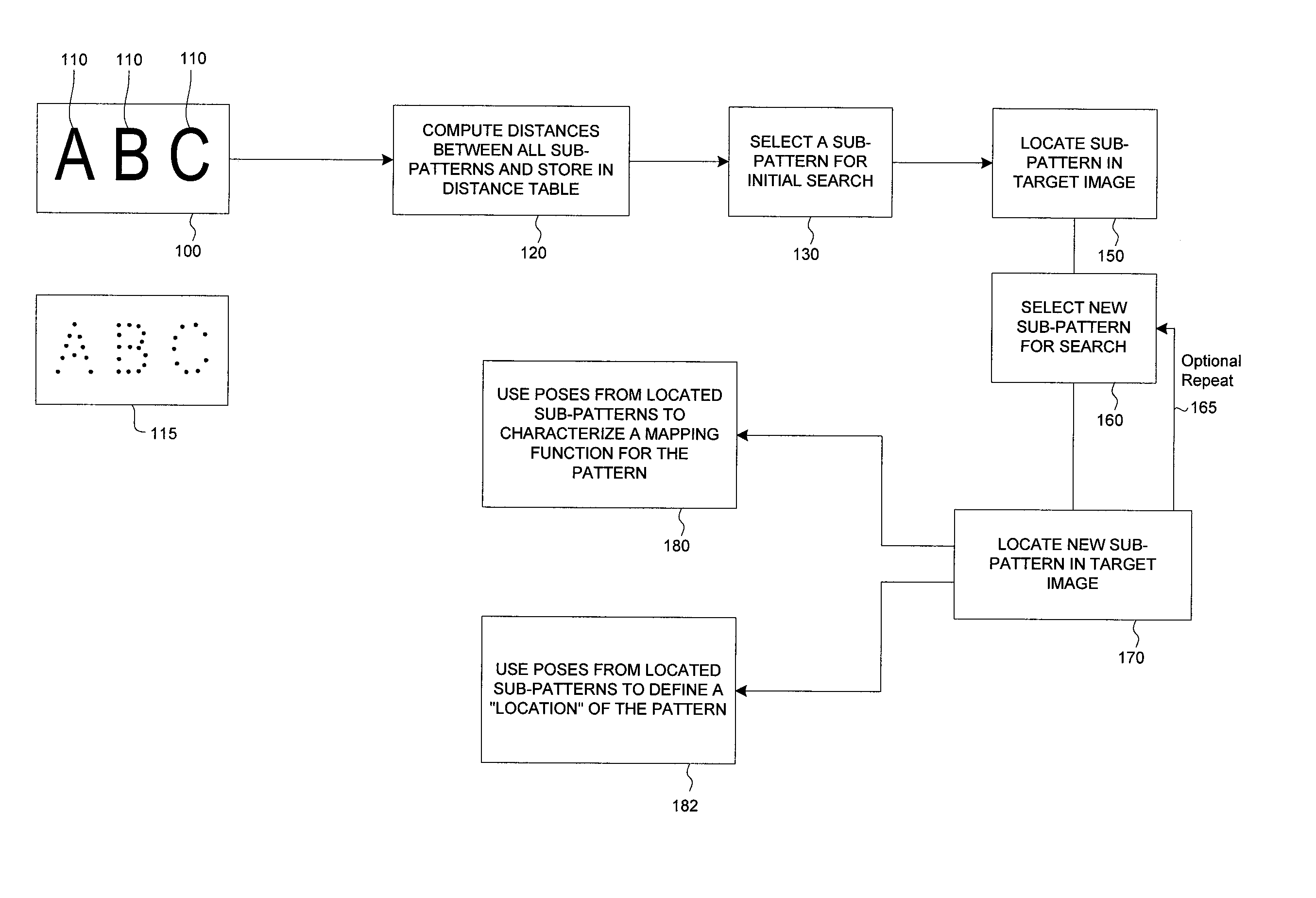
[0048]Referring to FIGS. 1 and 2, this method takes as input a target image having a pattern to be analyzed 100 (the letters A, B, and C, taken together), which is partitioned into a set of two or more sub-patterns 110 (the letters A, B, C; individually). These sub-patterns 110 are selected to be “spatially coherent” (a coherent sub-pattern tends to contain areas of the image that are connected to each other, and tends not to contain areas that aren't connected. For example, the region of the image where the “A”, lies in FIG. 2A is connected by virtue of being part of the “A”, so that would tend to be one coherent sub-pattern, but elements of the “B” would not be included because there is a gap such as in 205 between those elements), such that each sub-pattern 110 represents a particular region of the main pattern, and together the sub-pattern regions cover the majority of the area of the larger pattern 100 where pattern information, such as boundaries between light and dark regions...


PUM


Abstract

A method is disclosed for finding a deformed pattern in an image using a plurality of sub-patterns. By advantageously restricting sub-pattern search ranges, search speed is improved, and the incidence of spurious matches is reduced. The method also quickly decides which sub-pattern result, of several potential candidates, is most likely to be the correct match for a deformed sub-pattern. Also, a method is provided for characterizing a deformed pattern in an image by using results from feature-based search tools to create a mapping that models the deformation of the pattern. A transform, selectable by a user, is fit to the results from the search tools to create a global deformation mapping. This transformation is fit only to feature points derived from matches resulting from successful sub-pattern search, without including data from areas of the pattern that were blank, not matched, or otherwise didn't contain information about the pattern's distorted location.

Description

FIELD OF THE INVENTION[0001]This invention relates to machine vision systems, and particularly to methods for searching for a pattern in an image.BACKGROUND OF THE INVENTION[0002]The problem of how to find a particular pattern in an image is a well-known problem with many known solutions, such as feature-based search methods. Typically, the pattern is assumed to have undergone one or more of a few basic transformations, such as being scaled, or being rotated. However, these known solutions often fail if the pattern has been deformed by being warped, pulled, bent, wrinkled, damaged, or otherwise fundamentally changed from the original un-deformed shape that the search process is adapted to find.[0003]Nevertheless, even after transformation of the whole pattern, if the deformed pattern is divided into smaller sub-patterns, those sub-patterns are themselves fairly close in form to the corresponding parts of the original undeformed pattern. For example, if the pattern is bent into a “V”...

Claims


Application Information

Patent Timeline
Patent Type & Authority Patents(United States)
IPC IPC(8): G06K9/00G06K9/46G06K9/64
CPCG06T7/0079G06K9/6206G06V10/754
Inventor DAVIS, JASON
Owner COGNEX TECH & INVESTMENT
Learn More