

Display device
a display device and display technology, applied in the direction of instruments, static indicating devices, etc., can solve the problems of complex circuit structure of circuit costs, enlarged layout area of d/a converter circuit, yield decrease of display devices,
- Summary
- Abstract
- Description
- Claims
- Application Information
AI Technical Summary
Benefits of technology
Problems solved by technology
Method used
Image

Examples
embodiment mode 1
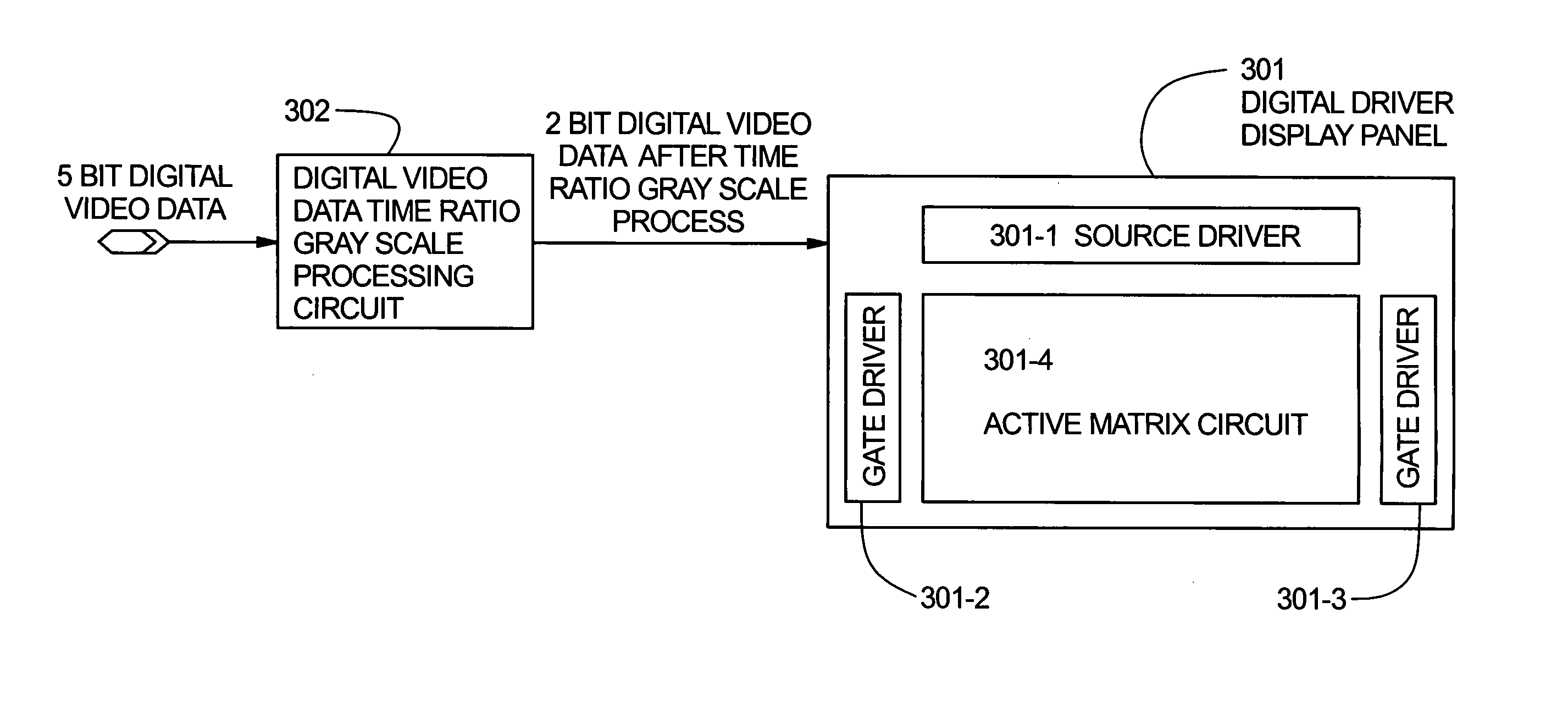
[0098]FIG. 3 schematically shows a structural diagram of a display device of this embodiment mode. In this embodiment mode, a display device to which 5 bit digital video data is sent from the external is taken as an example with the intention of simplifying the explanation.
[0099]Reference numeral 301 denotes a display panel having digital drivers. Denoted by 301-1 is a source driver, 301-2 and 301-3 are gate drivers, 301-4 is an active matrix circuit with a plurality of pixel TFTs arranged in matrix.
[0100]A digital video data time ratio gray scale processing circuit 302 converts, 2 bit digital video data of 5 bit digital video data inputted from the external into 2 bit digital video data for voltage gray scale method. Among the 5 bit digital video data, 3 bit gray scale information is expressed in time ratio gray scale.
[0101]The 2 bit digital video data underwent the conversion by the digital video data time ratio gray scale processing circuit 302 is inputted to the display panel 30...
embodiment mode 2
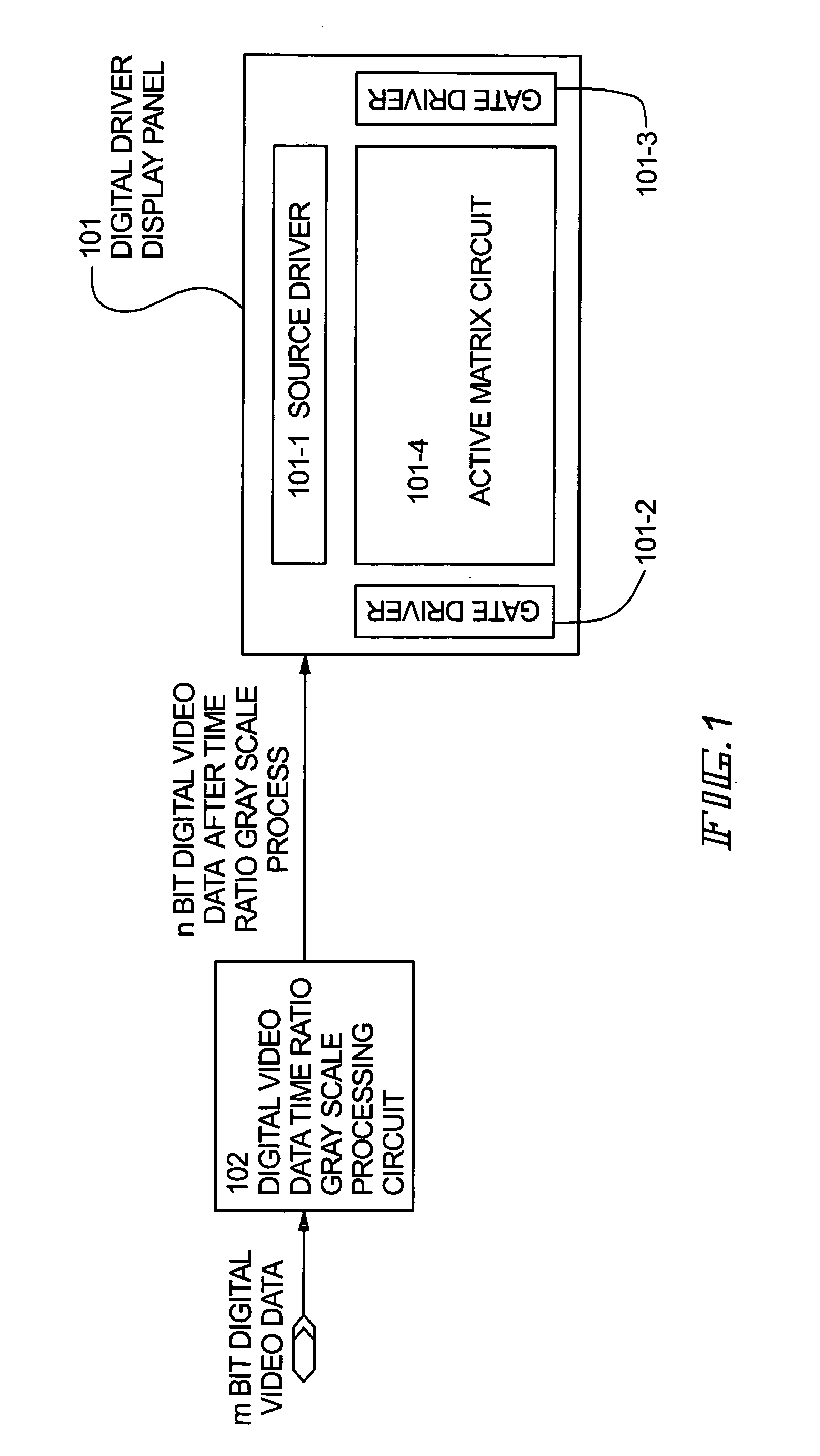
[0127]A description given in this embodiment mode is about a display device to which 8 bit digital video data is inputted. Reference is made to FIG. 9 that schematically shows the structure of the display device of this embodiment mode. Reference numeral 801 denotes a display device having digital drivers. Denoted by 801-1 and 801-2 are source drivers; 801-3, a gate driver; 801-4, an active matrix circuit with a plurality of pixel TFTs arranged in matrix; and 801-5, a digital video data time ratio gray scale processing circuit. The digital video data time ratio gray scale processing circuit is, as shown in the drawing, integrally formed in a display panel in this embodiment mode.
[0128]The digital video data time ratio gray scale processing circuit 801-5 converts, 6 bit digital video data of 8 bit digital video data inputted from the external, into 6 bit digital video data for voltage gray scale method. Gray scale information of 2 bit digital video data of the 8 bit digital video dat...
embodiment mode 3
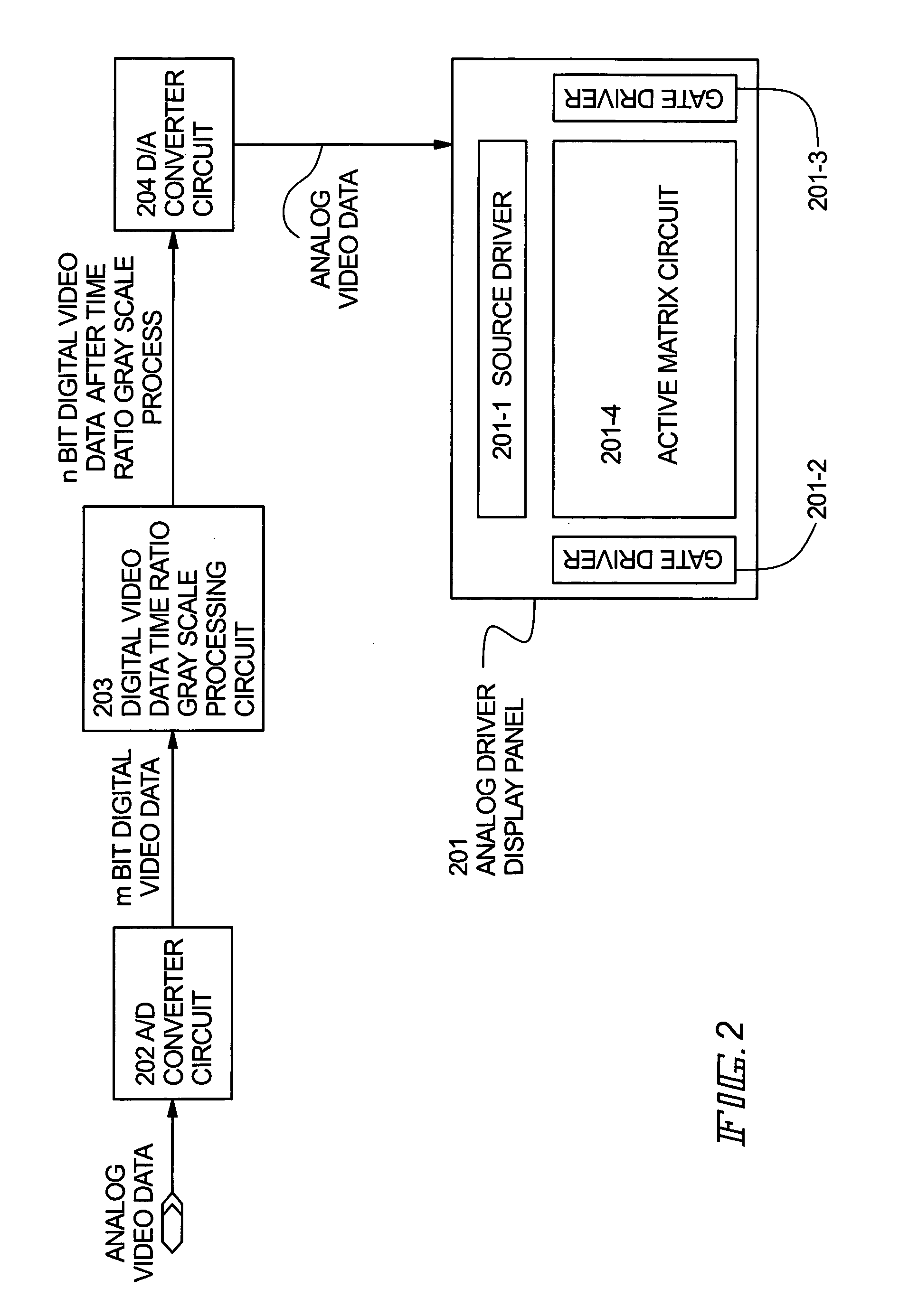
[0138]See FIG. 11. Reference numeral 1001 denotes a display panel having analogue drivers. Denoted by 1001-1 is a source driver; 1001-2 and 1001-3, gate drivers; 1001-4, an active matrix circuit with a plurality of pixel TFTs arranged in matrix.
[0139]A digital video data time ratio gray scale processing circuit 1002 converts, 2 bit digital video data of 5 bit digital video data inputted from the external, into 2 bit digital video data for voltage gray scale method. The gray scale information of 3 bit data of the 5 bit digital video data is expressed in time ratio gray scale.
[0140]The 2 bit digital video data converted by the digital video data time ratio gray scale processing circuit 1002 is inputted to a D / A converter circuit 1003 and converted into analogue video data. Then the analogue video data is inputted to the display panel 1001.
[0141]Here, a case when liquid crystal is applied as the display medium in the display device of the embodiment mode 2 is explained. Circuit structu...
PUM
 Abstract
Description
Claims
Application Information